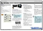
Tiger 320 Series Programming Code Sheet
Draft Copy. Code Version V3.08a
Texmate Inc. Tel. (760) 598 9899 • www.texmate.com
9
2 February, 2005 Prog. Code Sheet V3.08a (NZ101)
CODES 6 to 9
CH4 POST PROCESSING
0 Direct Display of Input (no pro-
cessing)
1 Square Root of Channel 4
2 Inverse of Channel 4
3
4 kilobits Meters
NO Linearization
32 kilobits Meters
32-point Linearization of CH4 using
Table 4
Note:
All linearization tables are set up
in the Calibration Mode [24X].
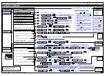
CODE 6 – CHANNEL 4 FUNCTIONS
FIRST DIGIT
SECOND DIGIT
THIRD DIGIT
FOR THERMOCOUPLE
0 Type J
1 Type K
2 Type R
3 Type S
4 Type T
5 Type B
6 Type N
7 For sensor tables other than those
listed above contact Texmate
FOR RTD TYPE (2-, 3-, 4- WIRE)
0 Resistance
1 Pt 385 100
Ω
RTD
2 Pt 392 100
Ω
RTD
3 Zn 120
Ω
RTD
4 Cu 10
Ω
RTD
MEASUREMENT TASK
0 No Function
1 Voltage, Current
2 TC
(3rd digit selects type of TC).
See Note 7
3 RTD/Resistance
(3rd digit selects type of RTD).
4 Real Time Clock and Timer
(3rd digit selects type)
5 -
6 -
7 Smart Input Module
(3rd digit selects register)
FOR SMART INPUT MODULE
0 Output Register 1
1 Output Register 2
2 Output Register 3
3 Output Register 4
4 Output Register 5
5 Output Register 6
6 Output Register 7
7 Smart Input Module
Register 3
Code Setup
RESULT PROCESSING
0 Direct Display of Result
as per processing per-
formed in 2nd and 3rd
digits
1 Square Root of Result
2 Inverse of Result
3 -
32-POINT LINEARIZATION FOR RESULT
0 No Linearization on Result
1 32-point Linearization on Result using Table 1
2 32-point Linearization on Result using Table 2.
See Note 5
3 32-point Linearization on Result using Table 3.
See Note 5
4 32-point Linearization on Result using Table 4.
See Note 5
5 125-point Linearization on Result (Tables 1 to 4 cascaded).
See Note 5
6 32-point Linearization on Result (Tables 1 to 4 selected
from the rear of the meter).
The selected table is not available if CH2, CH3, or CH4 is
operating in the analog mode. CH1 must be set to Voltage,
Current in Code 2 [X0X].
See Note 5
7 –
MATHS FUNCTIONS FOR RESULT
0 Result Register not Updated
1 pH Meter (CH1 = Tbuff, CH2 = pH)
2 Result = CH1, Setpoint 2 = CH2
3 Result = CH1 + CH2
4 Result = CH1 - CH2
5 Result = CH1 x CH2/10 000
6 Result = (CH1 x 20 000)/CH2
7 Result = CH1
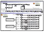
CODE 7 – RESULT PROCESSING
CODE 8 – DATA LOGGING AND PRINT MODE OPTIONS
FIRST DIGIT
SECOND DIGIT
THIRD DIGIT
DATA LOG BUFFER TYPE
0 No Data Logging
1 Cyclic
Buffer
2 Linear FIFO Buffer.
3 Reset Buffer Number to 0.
Note:
Setting Code 8 to [3XX] resets the
data log buffer to 0. Once reset,
Code 8 must be set back to the
required data log buffer setting.
DATE & TIME STAMP OPTIONS
0 Printer Format – No time stamp with
print/log
1 Printer Format – Time stamp format 1 [Mth-
Day-Yr Hrs:Min:Sec] (with <CR><LF>)
2 Printer Format – Time stamp format 2 [Day-
Mth-Yr Hrs:Min:Sec] (with <CR><LF>)
3 Printer Format – Time stamp format 3
[Hrs:Min:Sec] (with <CR><LF>)
4 Spreadsheet Format – No time stamp with
print/log
5 Spreadsheet Format – Time stamp format 1
[Mth-Day-Yr Hrs:Min:Sec]
6 Spreadsheet Format – Time stamp format 2
[Day-Mth-Yr Hrs:Min:Sec]
7 Spreadsheet Format – Time stamp format 3
[Hrs:Min:Sec]
ALL ABOVE ARE REAL-TIME CLOCK OPTIONS
LOG OR PRINT TRIGGER
0 No
trigger
1 Trigger on Demand from PRO-
GRAM Button
2 Trigger on Demand from F1 Button
3 Trigger on Demand from F2 Button
4 Trigger on Demand from HOLD Pin
5 Trigger on Demand from LOCK Pin
6 -
7 -
Note:
Log and/or Print will only trigger if
enabled.
DISPLAY TEST PIN
0 Display test only
1 Reset Counter Channel 1 and total
2 at Power-up
2 Reset Counters Channel 1, 2, 3, 4,
Total 1, and Total 2 at Power-up
3 Reset Total 1, and Total 2 at Power -up
HOLD PIN
0 Display
Hold
1 Reset Channel 1
2 Reset Total 1 and Total 2
3 Reset
Total
2
4 Reset
Peak,
Valley
5 Clear
Tare
6 Set Tare
7 Unlatch (de-energize) all Setpoints
LOCK PIN
0 Key
Lock
1 Reset Channel 1
2 Reset Channel 2
3 Reset Channel 3
4 Reset Channel 4
5 Clear
Tare
6 Reset Total 1
7 Unlatch (de-energize) all Setpoints
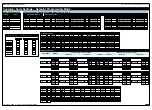
CODE 9 – FUNCTIONS FOR DIGITAL INPUT PINS
FOR REAL-TIME CLOCK & TIMER
0 HRS:MIN:SEC
1 HRS:MIN
2 -
3 -
4 1 Second Count UP Timer
5 1 Second Count DOWN Timer
6 -
7 -
P
Press
Note 5:
If only 4 kilobits of memory is installed,
only Table 1 is available for:
•
CH1 in Code 3, 2nd digit.
•
CH2 in Code 4, 3rd digit.
•
CH3 in Code 5, 1st digit.
•
CH4 in Code 6, 1st digit.
•
RESULT in Code 7, 2nd digit.
Note:
The function of the out-
put register selected
varies according to the
input module installed.
Use the
buttons to set the
required smart input module code
(0 to 377). See installed Input
Module data sheet for code details.
2
1
3
4
5
LOCK
HOLD
TEST
COMMON
CAPTURE
TERMINAL 2 – Function Pins
Programming Tip
For digital input functions selected in
Code 9 to operate, the relevant digital
input pin must be connected to the
COMMON pin on Terminal 2 of the
controller.
The example opposite shows the
HOLD pin (pin 1) connected to the
COMMON pin (pin 4) with the selected
function activated by a switch.


