4
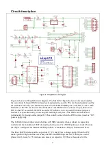
Vpp-before-Vdd sequence. Wisp648 can do this by generating the Vpp and then (very briefly)
shorting the 5V supply. This is done by the big transistor (TIP122) on the Wisp648 board. Some
target chips can not be programmed when this feature is active, and power supplies do not take this
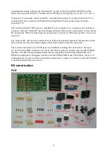
abuse well, so this feature can be disabled. To disable it you must remove the jumper on the pins
J1. I suggest that you leave that jumper out by default, unless you are sure that all your power
supply(s) can handle this. Your power supply must also limit the short-circuit current to a
reasonable value. A few Ampere or less will be OK. All supplies based on 7805, 78L05 and similar
chips have no problem with this. The Wisp648 has an on-board 7805-based power supply which
can handle this shorting.
Power
The Wisp648 is designed for programming a target PIC which uses 5V power. The Wisp648 needs
this 5V too. There are two possibilities for powering the Wisp648 and the target circuit:
•
The target circuit has its own 5V supply. Do not connect a wall-wart to the Wisp648; the
programmer will take its power from the target circuit.
•
The target circuit does not (yet?) have its own 5V. Connect a wall-wart to the Wisp648; the
programmer will supply 5V to the target circuit.
Do not mix the two situations, when both the target circuit and the Wisp648 supply 5V a small
difference in the two voltages might damage one or both power supplies.
The Wisp648 has an on-board 7805-based power supply. To use this supply you must connect an
external wall-wart that supplies 9 .. 18V DC. An AC wall-wart might work, but only for a target
circuit that uses very little current (< 100 mA). The wall-wart connector on the Wisp648 is a
2.5mm centre-pin connector, which is commonly used for wall-warts. The centre pin is positive,
which seems to be the most common polarity. Unfortunately, about 10 other connectors (and 1
other polarity) are also commonly used for wall-warts. If you prefer a more permanent and stable
connection (those centre-pin connectors disconnect very easily) you can use the PCB screw
connector block. The + mark on the PCB indicates where you must connect the positive wire.
The 7805 is a linear regulator, so the voltage difference between the input (from the wall-wart) and
the output (5V under normal circumstances, but could be 0V when you accidentally short-circuit
the power) will be dissipated as heat. The 7805 is short-circuit and thermally protected, so it should
withstand all normal use. But it might get (very) hot when you use it to supply a large current,
especially when combined with a high wall-wart voltage. The temperature rise can be calculated as
Λ
t
= ( V
in
– 5.0V ) * I * R
th
Λ
t
= temperature rise in degrees Kelvin
V
in
= Wall-Wart voltage
R
th
= thermal resistance, for a bare 7805: 60
o
K / W
I
= total current in A
With a common 12V DC wall-wart and 100mA ( = 0.1 A) total current the temperature rise will be
42
o
K, which is reasonably safe. For a higher current and/or a higher input voltage you might want
to attach a heatsink. A small heatsink might have an R
th
of 20
o
K / W, which rises the safe current
by a factor of 3. For a heatsink with a still lower thermal resistance the internal thermal resistance
of the 7805 must be taken into account (check the datasheet).
The Wisp648 contains a diode (D4, 1N5819) that will short the +5V power when it is supplied by
the target circuit but accidentally connected in reverse. This diode can handle 1A, probably more
for a short time. You of course will never apply power in reverse (I do), but just in case, it might be
a good idea to use a power supply that is current-limited to 1A or less. In fact 100 mA will be


