5
enough for most ‘beginners’ projects. Using a switching power unit from a PC is a very bad idea;
such a PSU can deliver currents that are more appropriate for an arc welder than for an electronic
project.
Serial pass-through
The Wisp648 can connect your serial port directly to the target chip. This can be very convenient:
after programming your target chip you can communicate with it, using the same serial port,
without re-plugging cables or other manual actions. This pass-through is done in the Wisp648
firmware, so it is limited to lower baudrates (up to 9600 baud seems to work OK). In-circuit
programming requires two wires data between the programmer and the target chip, so it makes
sense to re-use those two wires for serial communication. But the two PIC pins used for in-circuit
programming are not the pins used by the PIC UART, so using these two pins forces you to use
software (bit-banged) UART code in your target chip. The Wisp648 has two extra lines that are not
used for programming the chip, but can be connected to the target chip UART pins. This requires
you to make two extra connections, but now you can use the hardware UART in your target chip.
(That is, if it has one. Not all PIC chips do.)
Note that the two extra lines (for connection to the PICs UART pins) are available only on the
DB15 programming connector. The ICD2 and PICkit2 programmers do not have a pass-through
function, so no pins are available on these connectors for such a function.
The common asynchronous serial communication (as used by the PC serial port) uses RS232
voltage levels and polarity. These PIC UART pins use TTL (0 .. 5V) levels and inverted polarity
(inverted with respect to the RS232 line levels). A MAX232 or an equivalent chip is the standard
way to interface between the TTL signals and the RS232 signals. But some dirt-cheap PIC circuits
interface the PIC pins directly to the RS232 signals. This violates all design rules and
specifications, but sometimes it works. Note that in this situation the TTL signals have the same
polarity as the RS232 signals. Hence a PIC UART can not be used, because it uses inverted
polarity.
The Wisp648 pass-through function interfaces between the signals on its RS232 connector and the
target chip. Two choices are available:
•
Use the programming lines (PGM and PGD) or use the extra lines (pin 7 and 8 of the DB15
connector)
•
Use inverted polarity (the target PIC assumes that it interfaces to RS232 via a level/polarity
converter – MAX232 or similar), or use true polarity (the target PIC assumes that it
interfaces directly to RS232).
I recommend using inverted polarity: true polarity makes sense only for dirt-cheap circuits and its
reliability is questionable. The choice between using the UART or bit-banging the serial
communication on the PGC/PGD lines is up to you. The UART is easier to program, but the
UART is not present on all PICs, and it requires two extra wires, which are available on the DB15
connector only. Using the PGC/PGD lines requires more work on the target chip, but needs no
extra wires and allows the use of the ICD2 or PICkit2 compatible programming connectors.
When the target circuit itself has an RS232 interface and you want to ’take over’ this interface with
the Wisp648 pass-through feature a resistor must be inserted to make it possible for the Wisp648 to
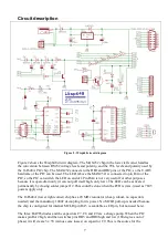
‘override’ the signal from the RS232 level converter. I suggest a value of 1 .. 10k. Figure 1
illustrates this trick. It also shows isolation resistors between the PGM, PGC and PGD lines and the
rest of the target circuit, a 33k pull-up for the MCLR pin, and the mandatory 100nF decoupling
capacitor for the power.


