background image


Appendix 1 Modbus Protocol

37

TI 01W01A56-01EN

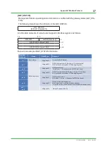
[GW_STATUS]

Management Station operating status information is notified with the gateway status (GW_STA-

TUS).
The following table shows the attributes of the GW_STATUS.

GW_STATUS

(32bit x 8 : Unsigned16)

And the data elements of a device are mapped to Modbus registers as follows.

16

8 7

0

00000000

0x0080 (Reserved)

n

GW_STATUS (Upper 16bit)   

n+1

~

~

GW_STATUS (Lower 16bit)

n+8

Below is an example of GW_STATUS information. 

Modbus

Address 

Name

Data Type 

Contents

n

Data status 

Unsigned16

Always 0x0080: Normal

n +1

Gateway status

Unsigned16

GW0/1 system error (0: No error, 1: Error detected)

GW1 in redundant system, GW0 in single system

Unsigned16

GW2 system error

(0: No error, 1: Error detected, 0xFFFF:Not used)

n +2

Unsigned16

GW0/1 system status (0: Ready, 1: Active, 2: Standby)

GW1 in redundant system, GW0 in single system

n +3

Unsigned16

GW2 system status 

(0: Ready, 1: Active, 2: Standby, 0xFFFF:Not used)

n +4

n +5

Unsigned16

Status of field wireless device

0: No error (Join for all  field wireless devices)

1: Error detected. (Leave for one or more field wireless devices)

n +6 

~

n +8

Unsigned16

Always 0 (Reserved bits)

Mar. 31, 2014-00

Summary of Contents for YFGW410

Page 1: ...able 11 2 3 1 Connecting Field Wireless Management Station Cable 11 2 3 2 Connecting Field Wireless Access Point Cable 12 2 3 3 Connecting Grounding Wire 13 2 4 Mounting Antenna 15 3 Configuration 16...

Page 2: ...onsole FWMC R1 03 01 and FieldMate R2 05 Notes This startup guide may be revised periodically to incorporate updated information Please use a computer s administrator account to install or update the...

Page 3: ...cquired by the Host System via Field Network The system configurations parameters are modified by Field Wireless Management Console FWMC which is Web based software without installation and is used on...

Page 4: ...nna Mounting Step 2 Configuration Chapter 3 PC Network Configuration Wireless System Configuration Device Provisioning YFGW510 Initial Configuration Provisioning File Registration Download New Configu...

Page 5: ...oint Initial Configuration Parameters Before provisioning a Field Wireless Device decide the Network ID and the Device Tag Table 1 Device Provisioning and Access Point Initial Configuration setting It...

Page 6: ...ration Field Network 3 Not used in this configuration Access Control Lists Not used in this configuration Time Sorce Not used in this configuration Operation Mode Not a configurable parameter Hopping...

Page 7: ...ngs Chap General settings 3 2 5 Properties Device Tag YTA510_1 Device Role IO Auto Primary Router Not used in this configuration Secondary Router Not used in this configuration Not online Use default...

Page 8: ...ad ditional information Table 4 Modbus setting Absolute Address Input Register Number Allocation Data Type words 30001 0 Status Unsigned16 x 1 30002 30003 1 2 DIAG_STATUS Unsigned32 x 2 30004 3 Data...

Page 9: ...r driver Device Provisioning Install the driver from Infrared adapter accessary DVD ACTiSYS Infrared Adapter ACT IR224UN 9600bps 4 YFGW510tool Initial setting for Access Point Copy the software from Y...

Page 10: ...or 24 bits or more recommended Resolution 1280 x 800 recommended Network port Ethernet compatible network ports FieldMate Basic Advance Operating System Windows 7 Professional Home Premium 32bit 64bit...

Page 11: ...ector 4 LED Indicator RDY Green Field Wireless Management Station Terminator of Cable for Redundancy Synchronization connector Power supply connector Field network interface 1 Connect Ethernet cable f...

Page 12: ...ication RJ 45 connector Field wireless backbone interface 1 Connect Ethernet cable from Management Station B1 Backbone Interface to Access Point 2 Insert the power supply cable through the power suppl...

Page 13: ...f the main body and the ground terminal at the power supply spring terminal Ground terminal Power supply connector RS 485 connector Ground Connect the ground cable from the frame ground FG terminal to...

Page 14: ...round terminal of Access Point The ground terminal is lo cated at the bottom on the right side of the housing Class D grounding the third class grounding with the ground resistance of 100 ohms or less...

Page 15: ...ctor on the top of the device Ensure that the antenna is properly mounted 1 Turn counter clockwise the cover of the antenna connector on the top of YFGW510 to re move 2 Mount the provided antenna into...

Page 16: ...Wireless System Field Network Register NetworkID Register BBR Register Device Modbus Mapping Hopping Pattern 1 2 3 4 5 6 Start Configurator Start Field Wireless Management Console over a web browser...

Page 17: ...le 1 and configure the Field Network s IPAddress Factory Default ip 192 168 0 101 sm 255 255 255 0 dg 192 168 0 101 3 2 2 Network ID Registration Field Network Register NetworkID Register BBR Register...

Page 18: ...pping Pattern Configuration items for Network ID 1 Click Network ID 100 from Menu tree in the left pane and click Backbone Routers tab 2 Click Add and enter BBR001 in Device Tag to register an initial...

Page 19: ...ping Hopping Pattern Configuration items for Network ID 1 Click Hopping Patterns from Menu tree in the left pane 2 Click the checkbox and enable pattern A and click Optimization 3 Click created Networ...

Page 20: ...Network ID 1 Click Field Devices tab and click Add to register Field Wireless Device 2 Enter YTA510_1 in Device Tag select Device Role IO Auto and click OK 3 Click Sampling Data from Menu tree in the...

Page 21: ...older below Click the pull down menu again and select the CF file for Field Wireless Device YTA510 C Yokogawa FieldWireless FieldWirelessConfigurator CFDD 59543 0005 7 Enter 10 sec in Publication Peri...

Page 22: ...gs from Menu tree in the left pane 2 Click Normal Mapping as the Mapping type 3 Map the process data parameters to the registers of the Management Station according to the Table 4 Drag and drop the DI...

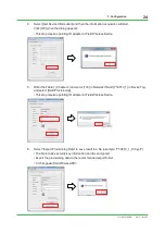
Page 23: ...ic network 1 Connect the infrared adapter to Configuration Monitoring PC Make sure that the distance between infrared adapter and infrared communication port on the front of the Field Wireless Device...

Page 24: ...he Table 1 Chapter 2 and enter 100 in Network ID and YTA510_1 in Device Tag and select Start Provisioning This step requires pointing IR adapter at Field Wireless Device 6 Select Export Provisioning D...

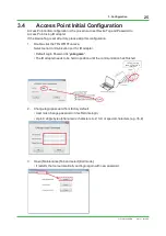
Page 25: ...Default Login Password is yokogawa The IR adapter needs to be held in position until the communication has finished If there is a tag name YFGW510 is initialized Field wireless access point setup tool...

Page 26: ...5 Enter BBR001 in Device Tag and click Save to finish initial configuration Up to 16 single byte alphanumeric characters A Z 0 9 and special characters under score and hyphen BBR001 7 Open Maintenance...

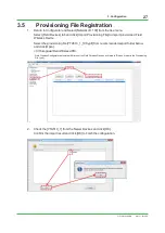
Page 27: ...eld Wireless Device Select the provisioning file YTA510_1_100 ypif from recommended export folder below and click Open C Yokogawa Field Wireless PD Field Wireless Configurator automatically filters ou...

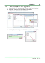
Page 28: ...in the menu bar And then Error Check process automatically starts 2 Select Start download and click OK to download the new setting Devices need to reboot will be automatically checked 3 Click OK after...

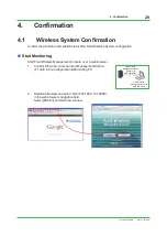
Page 29: ...eld Wireless Management Console over a web browser 1 Confirm Ethernet connection from Management Station F1 port to the Configuration Monitoring PC 2 Start web browser and enter http 192 168 0 101 808...

Page 30: ...t and confirm status below for Management Station and Access Point YFGW410 Management Station GW Join Status Full join BBR001 Access Point Join Status Full join 4 1 2 Field Device List Field Device Li...

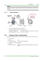
Page 31: ...ED and LCD indicators Management Station YFGW410 RDY LED Green Access Point YFGW510 ACTLED Green LAN LED Green Blink ISA Green Blink Field Wireless Device YTA510 Status bar Published 4 2 Backup Files...

Page 32: ...less network The field wireless devices transmit data via the Access Point which is the central device in the network The Access Point further relays to the gateway Gateway includes system manager rol...

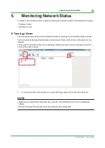
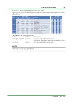
Page 33: ...the Tab menu 2 Confirm the RSSI P PER P column Join Count is indicated in the bracket at Join Status and it shows the total number of joins per device NOTE It takes approximately 30 min to indicate RS...

Page 34: ...ms system engineering is required to embed the error detection mechanism us ing Device Status of each wireless system component Process Data Status and self diagnosis status DIAG_STATUS of the field w...

Page 35: ...uality 0x80 128 Good condition without error Example of wireless communication status Not Join 0x08 8 Not Connected Removing Battery LEAVE 0x14 20 No Communication with Last Usable Value User specific...

Page 36: ...gned16 DIAG_STATUS 32bit Unsigned32 DIAG_STATUS is mapped as below with 8bit reserved space 16 8 7 0 00000000 Status 8bit DIAG_STATUS Upper 16bit DIAG_STATUS Lower 16bit Below is an example of DIAG_ST...

Page 37: ...Name Data Type Contents n Data status Unsigned16 Always 0x0080 Normal n 1 Gateway status Unsigned16 GW0 1 system error 0 No error 1 Error detected GW1 in redundant system GW0 in single system Unsigne...

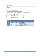
Page 38: ...16 And the data elements of a device are mapped to Modbus registers as follows 16 8 7 0 00000000 0x0080 Reserved n BBR_STATUS Upper 16bit n 1 BBR_STATUS Lower 16bit n 8 Below is an example of BBR_STAT...

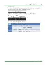
Page 39: ...pped to Modbus registers as follows 16 8 7 0 00000000 0x0080 Reserved n DEV_STATUS Upper 16bit n 1 DEV_STATUS Lower 16bit n 8 Below is an example of DEV_STATUS information Modbus address Name Data for...

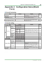
Page 40: ...to connect Management Station and the Configuration Monitoring PC through Ethernet Do not use identical IP addresses on the same Ethernet 3 2 2 Subnet Mask Default Gateway Field Net work 2 Not used in...

Page 41: ...Wireless De vice 3 2 5 Graphic Editor Not used in this configuration Alert Setting Use default setting Sampling Data See Table 3 Configuration items for Field Wireless De vice 3 2 5 Modbus Settings S...

Page 42: ...efault setting Device Group Not used in this configuration Sampling Settings Device Tag A name assigned to the Field Wireless De vice for identifying the device CF DD CF File Confirm the appropriate r...

Page 43: ...words Status Unsigned16 x 1 DIAG_STATUS Unsigned32 x 2 Data Status Unsigned16 x 1 PV Float x 2 Data Status 1 Unsigned16 x 1 GW_STATUS Unsigned16 x 8 Data Status 1 Unsigned16 x 1 BBR_STATUS Unsigned16...

Page 44: ...01W01A56 01EN Revision Information Document Name YFGW410 Field Wireless Management Station Startup Guide Document Number TI 01W01A56 01EN Edition Date Page Revised Item 1st Mar 2014 New issue Mar 31 2...

Reviews: