Chapter 9 IPv6 Route-Map Policy Configuration
directly-connected routes to peer CE1. VRF test1 that resides on PE2 advertises the
Address routes generated by the local Loopback address and directly-connected routes
to peer CE2. The VRF test1 routing table on PE1 and PE2 contains the local and remote
routes.
The route-map, used for VRF test1 on PE1, allows PE1 to import or export routes from/to
its VPN neighbor.
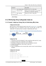
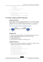
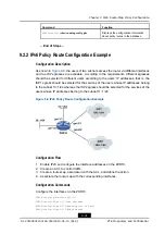
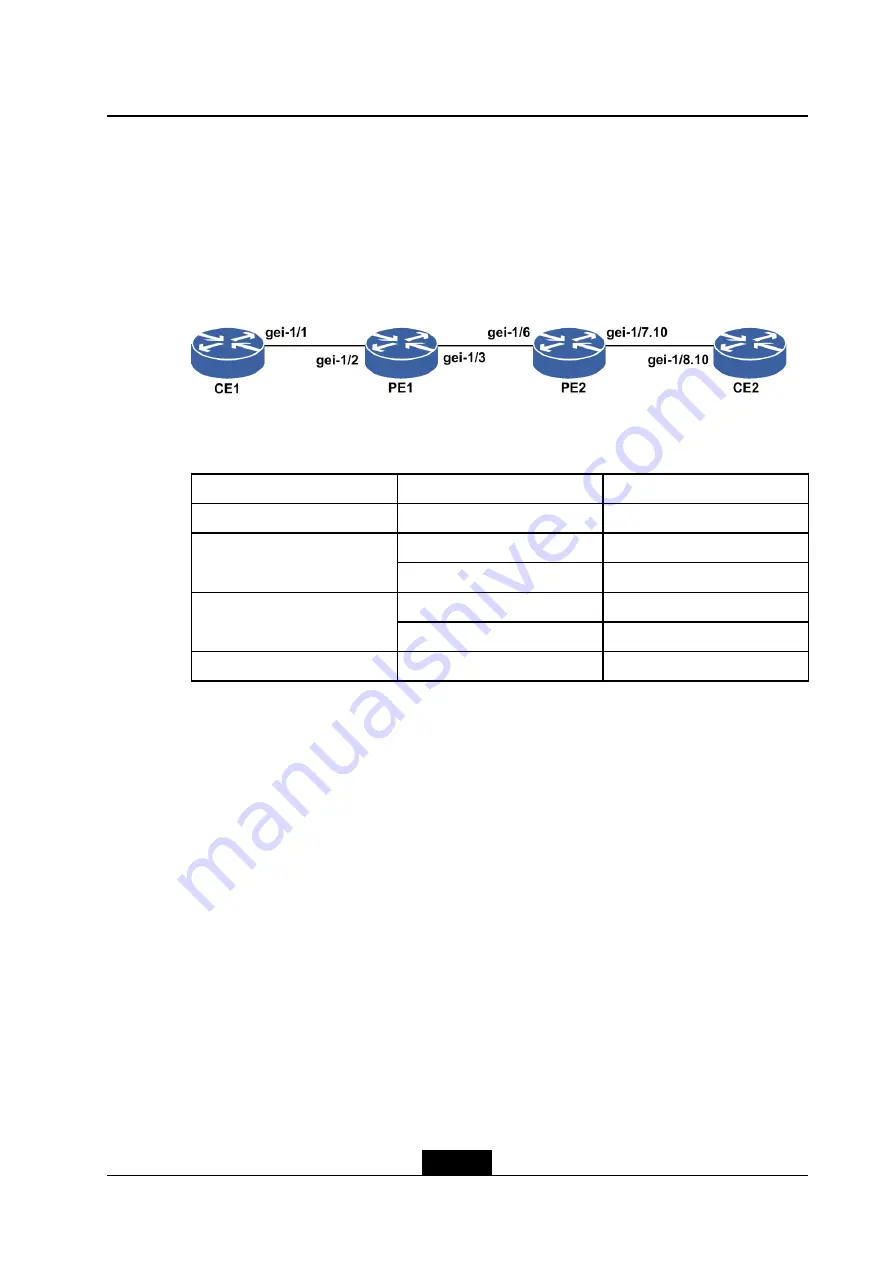
Figure 9-5 An Example of Configuring a Routing Policy for 6VPE
lists an IP address planning.
Table 9-1 IP Address Planning
Equipment
Interface
IP Address
CE1
gei-1/1
1001::20:2/120
gei-1/2
1001::20:1/120
PE1
gei-1/3
10.10.12.1/24
gei-1/6
10.10.12.2/24
PE2
gei-1/7.10
2002::20:2/120
CE2
gei-1/8.10
2002::20:1/120
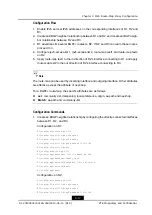
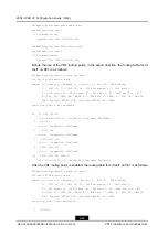
Configuration Flow
1.
Configure the basic L3VPN networking environment (CE1–PE1–PE2–CE2), enable
IPv6 and set IPv6 addresses on the corresponding interfaces of the routers.
2.
Configure the protocol, and make sure that the private routing tables on two PEs
contain all planned routes.
3.
Create a route-map on PE1, and define the characteristics of the routes for which
policy routing is performed (that is, defining a group of match criteria). Various route
attributes, such as destination address, can be grouped as a match rule.
4.
Apply the route-map to a VRF instance on PE1 to implement route importing/exporting,
route publishing and receiving.
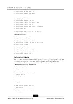
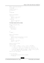
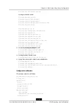
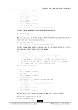
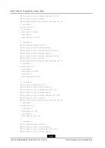
Configuration Commands
1.
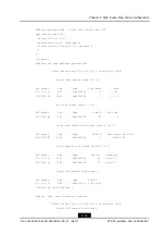
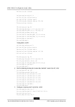
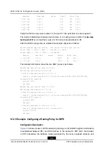
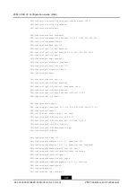
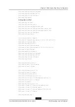
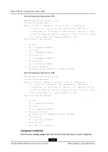
Configure the basic L3VPN networking environment on PE1 and PE2.
Configuration on PE1:
PE1(config)#ip vrf test1
PE1(config-vrf-test1)#rd 100:1
PE1(config-vrf-test1)#address-family ipv6
PE1(config-vrf-test1-af-ipv6)#route-target import 100:1
9-21
SJ-20140504150128-018|2014-05-10 (R1.0)
ZTE Proprietary and Confidential

