Agilent 4155B/4156B VXIplug&play Driver User’s Guide, Edition 4
4-21
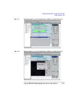
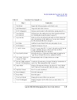
Sample Application Programs for HP VEE
Using sample2.vee
Table 4-4
Execution Flow of sample2.vee
Object
Explanation
1
Until Break
Repeats the following sequence until a break occurs.
2
Start Measurement
Triggers the start of the wafer test.
3
H/W Configuration
Defines execution mode. Set the mode before running sample2.vee.
4
Save Directory,
Init G data dir
Defines name of the subdirectory to save measurement result data.
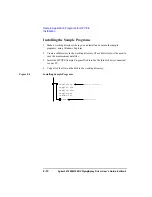
See “Installing the Sample Programs” on page 10.
6
Save Info File
Defines and saves the information file (info.txt) which contains title,
date, and comments for the subdirectory. You can enter comments.
See “Measurement Data Files” on page 8.
7
Init Prober
Initializes Cascade Summit series semi-auto prober, if used.
8
Init Instrument
Initializes instruments, if used.
9
1, Init G 1st meas
Sets G_1st_meas value. If G_1st_meas=1, the prober sets the first die
to probe, and header lines are written in vth1.txt and vth2.txt.
See “Measurement Data Files” on page 8.
10
Goto Next Die, Break
Probes the die to test. The die and probing sequence depend on the
*.ppd file used. Breaks if the test was completed for all die.
11
Get G xidx, Get G yidx
Current X, Y Index
Gets and displays the X-Y index of the die now tested.
13
Device1 Vth Measurement
Device2 Vth Measurement
Executes Id-Vg measurement, extracts Vth, and saves measurement
results. See “Measurement Data Files” on page 8.
14
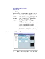
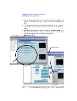
Show Result
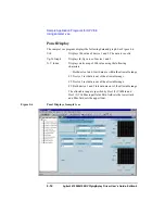
Displays Vth value and wafer map. See Figure 4-11. Dev1 Vth and
Dev2 Vth show Vth value, and the field below shows wafer map.
15
Update G 1st meas
Sets G_1st_meas variable to 0.
16
Reset Instrument
Resets the instruments.
17
Reset Prober
Resets the prober.
--
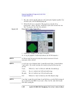
View Vg-Id Graph
Displays Id-Vg curve of the device you select.
--
View Vth Histogram
Displays histogram for Vth of the device you select (device 1 or
device 2).


