GEM80
6. Maintenance and Fault Finding
Issue 002 (07/05)
Fieldbus Technical Manual T2035
Page 13
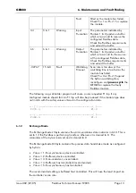
Fault
fitted or the module has failed.
Check Pn+1 or Pn+17 or replace
the module.
34
5 & 1
Warning
Input
Truncation
The parameters indicated by
Pointers 1 & 2 produce a buffer
which is too small to receive the
configured Fieldbus data.
Check the Fieldbus requirements
and extend the buffer.
66
6 & 1
Warning
Output
Truncation
The parameters indicated by
Pointers 1 & 2 produce a buffer
which is too small for the source
of the configured Fieldbus data.
Check the Fieldbus requirements
and extend the buffer.
-32767
15 & 0
Fault
Watchdog
Timeout
Scan rate is too slow or the
watchdog time is too fast or the
module has failed.
Check Pn+3 or Pn+19 against
the SyCon watchdog time,
reconfigure and
power-cycle
the
GEM80 or replace the faulty
Fieldbus module
The following rungs of ladder program will cause a user requested F1 trip if any
configured module should fail. An F1 trip will also be produced if the module type does
not match with the safety values entered in the configuration data.
---] [------------------------------------( )---
F372.4 F1.0
---] [------------------------------------( )---
F386.4 F1.1
6.1.2
Exchange Mode
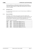
The Exchange Mode LS byte contains the communications state indicator in bit 0. This is
set to 1 if the Fieldbus is performing transfers; otherwise it is cleared to 0. The
remainder of the byte is reserved and is cleared to 0.
The Exchange Mode MS byte contains the process data handshake mode as configured
by SyCon.
•
Value = 1. Bus synchronous, device controlled.
•
Value = 2. Buffered, device controlled.
•
Value = 3. Non-consistent, uncontrolled.
•
Value = 4. Buffered, host controlled (recommended).
•
Value = 5. Bus synchronous, host controlled.
The recommended setting is buffered host controlled. This will have the least impact on
the controller’s scan rate.


