Outdoor LoRa Data Logger
35
2.3 I/O Configuration
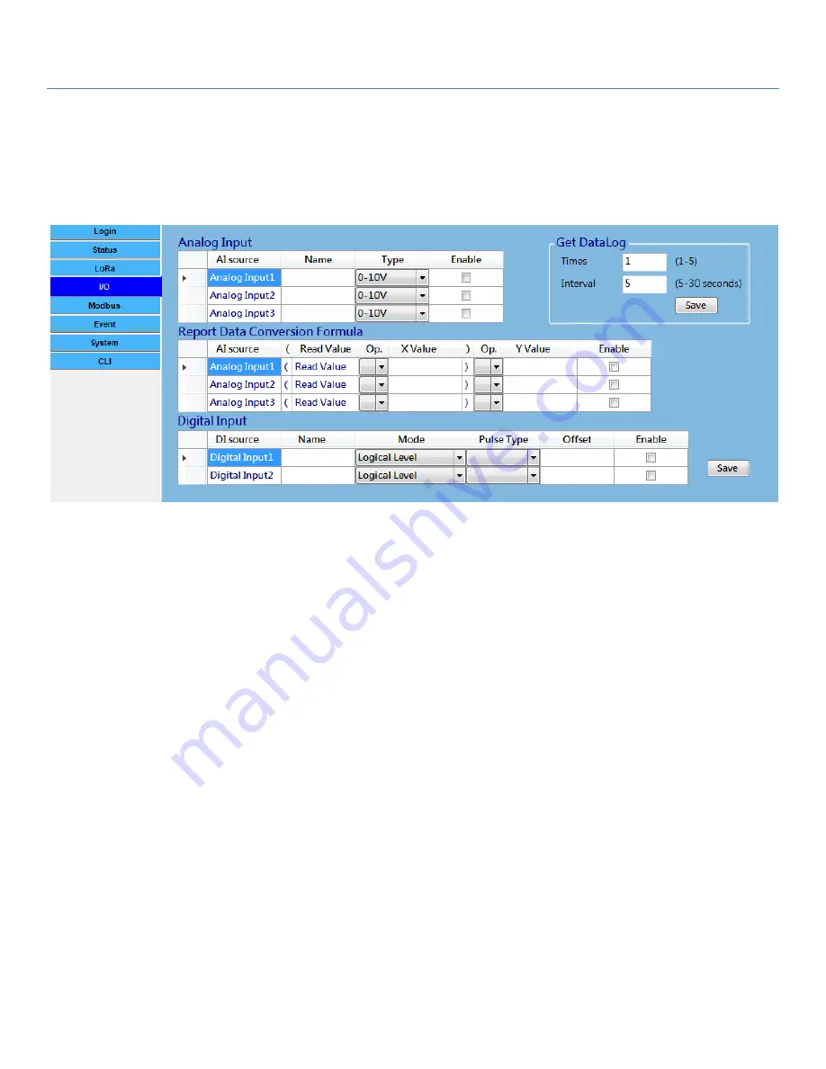
In the I/O Configuration screen, you can configure the Analog Inputs (AIs) and Digital Inputs (DIs). There are 3
sets of AIs and 2 sets of DIs.
According to the hardware configuration you already finished, you have to further configure the settings for
the device firmware, so that the Data Logger will know what kind of input device is connected to each port.
For Analog Input ports, you can specify an optional
Name
for identification, and the
type
for each connected
port. And then click
Enable
check boxes for those connected ports. The available AI types can be
0-10V
,
0-20V
,
or
4-20mA
, but it depends on specific product specification.
In addition, the AI value read from A/D converter can be further transform to a physical value for the real
world, like the temperature, or water level. You can specify a simple data conversion formula with the base
fromat:
Physical Value
= (
Read Value
Op.1
X
) Op.2
Y
, where
Read Value
: the input value (ex. 7.5V or 12.4mA) for a certain AI signal.
Op.1 and Op.2: both op. can be ‘+’ or ‘*’;
X
and
Y
: both values can be any real number range from -65535.00 to 65535.00.
For Digital Input ports, you can specify an optional
Name
for identification, and the
Mode
(
Logical Level
, or
Pulse Counter
) for each connected port. And then click
Enable
check boxes for those connected ports.
If
Pulse Counter
mode is selected, some additional fields (
pulse type
and
Offset
value) have to further define.
Pulse Type
: It can be
Change
,
Rising
, or
Falling
. On each pulse event, the corresponding internal
counter will be increased by 1 automatically.


