BH8-Series – User’s Manual
support@barrett.com
www.barrett.com
© 2007 Barrett Technology®, Inc.
Document: D3000, Version: AF.00
Page 67 of 82
-100
-75
-50
-25
0
25
50
75
100
-1
-0.75
-0.5
-0.25
0
0.25
0.5
0.75
1
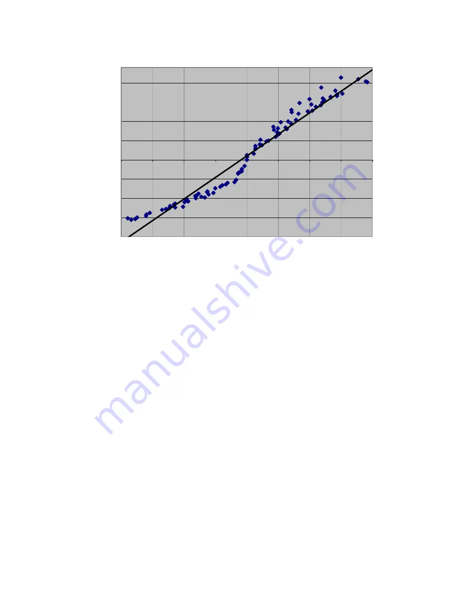
Torque About Joint 3 (N-m)
D
e
lt
a
S
tr
a
in
G
a
u
g
e
V
a
lu
e
s
Figure 28 - Strain Gage Torque Curves
Note: In Figure 28, true SG values have been adjusted so that the no-load value corresponds to
zero torque. If the torque curve measured does not approximate the torque curve shown in Figure
28, see Section 8. The torque curves for each finger will be different due to the variations in
materials.
9.5 Kinematics
The kinematics for the BarrettHand™ were determined using the Denavit - Hartenberg notation
described in "Introduction to Robotics, Mechanics and Control 2
nd
Edition", John J. Craig. Each
finger is considered its own manipulator and is referenced to a wrist coordinate frame in the center
of the palm. Use the forward kinematics calculated in this section to determine fingertip position
and orientation with respect to the palm.
Equation 1 is used to determine the transforms between axes i and i-1.
−
=
Τ
−
−
−
−
−
−
−
−
−
1
0
0
0
c
c
s
s
-
c
s
a
0
s
-
c
1
1
1
i
1
i
1
1
1
i
1
i
1
-
i
i
1
i
i
i
i
i
i
i
i
i
i
i
i
i
d
c
s
s
d
s
c
c
α
α
α
θ
α
θ
α
α
α
θ
α
θ
θ
θ
Equation 1 - Homogeneous Transform Between {i-1} and {i}
Where:
A
i-1
= distance from z
i-1
to z
i
measured along x
i-1
α
i-1
= angle between z
i-1
to z
i
measured about x
i-1
d
i
= distance from x
i-1
to x
i
measured along z
i


