Commissioning
EL125x, EL2258
138
Version: 2.5
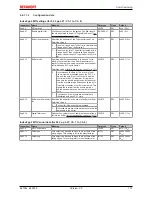
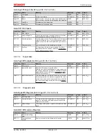
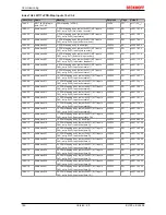
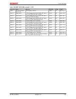
Index 8pp0 TSI Settings (for 08 ≤ pp ≤ 0F; Ch. 1 to Ch. 8)
Index (hex) Name
Meaning
Data type
Flags
Default
8pp0:0
TSI Settings
UINT8
RO
0x02 (2
dec
)
8pp0:01
Pos Sample Mode
During each PLC cycle only one rising edge may be
detected at the terminal input. If several edges arrive
during a cycle, this bit can be used to decide which
edge should be shown in the process image.
Permitted values:
BIT1
RW
0x00 (0
dec
)
0
Last edge: The last edge of the preceding PLC
cycle is shown
1
First edge: The first edge of the preceding PLC
cycle is shown
8pp0:02
Neg Sample Mode
During each PLC cycle only one falling edge may be
detected at the terminal input. If several edges arrive
during a cycle, this bit can be used to decide which
edge should be shown in the process image.
Permitted values:
BIT1
RW
0x00 (0
dec
)
0
Last edge: The last edge of the preceding PLC
cycle is shown
1
First edge: The first edge of the preceding PLC
cycle is shown
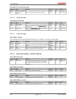
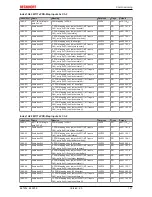
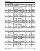
Index 8ppF TSI Vendor data (for 08 ≤ pp ≤ 0F; Ch. 1 to Ch. 8)
Index (hex) Name
Meaning
Data type
Flags
Default
8ppF:0
TSI Vendor data
UINT8
RO
0x12 (18
dec
)
8ppF:11
Offset pos
This object can be used to move the input time of the
rising edges. This setting is left to the manufacturer.
INT32
RW
0x00000000
(0
dec
)
8ppF:12
Offset neg
This object can be used to move the input time of the
falling edges. This setting is left to the manufacturer.
INT32
RW
0x00000000
(0
dec
)
6.8.1.1.3
Input data
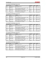
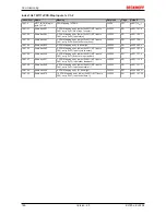
Index 6pp1 MTI inputs (for 00 ≤ pp ≤ 07; Ch. 1 to Ch. 8)
Index (hex) Name
Meaning
Data type
Flags
Default
6pp1:0
MTI inputs
UINT8
RO
0x00 (0
dec
)
6pp1:01
No of input events
Signals the number of new timestamps available in the
process image. If three is returned, for example, only
the objects "Input event state 1...3" and "Input event
time 1...3" are valid.
UINT8
RO
0x00 (0
dec
)
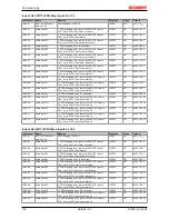
6pp1:09
Input state
Indicates the current input state at the time of the
process data cycle.
BOOLEAN
RO
0x00 (0
dec
)
6pp1:0A
Input buffer overflow
More events occurred at the input than elements were
free in the buffer for the channel.
BOOLEAN
RO
0x00 (0
dec
)
6pp1:0F
Input cycle counter
Is incremented with each process data cycle and
switches to 0 after its maximum value of 3.
BIT2
RO
0x00 (0
dec
)
6pp1:11
Events in input buffer
Signals the number of events currently in the buffer.
UINT8
RO
0x00 (0
dec
)
6pp1:12
Input order feedback
This byte reflects the state of the "Input order counter"
byte
(further explanation see here) [
}
122]
.
UINT8
RO
0x00 (0
dec
)
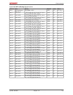
6pp1:21
Input event state 1
Indicates whether the event was a rising (1) or a falling
(0) edge.
BOOLEAN
RO
0x00 (0
dec
)
6pp1:22
Input event state 2
...
BOOLEAN
RO
0x00 (0
dec
)
6pp1:2A
Input event state 10
...
BOOLEAN
RO
0x00 (0
dec
)
6pp1:41
Input event time 1
32-bit timestamp for the corresponding "Input event
state n"
UINT32
RO
0x00000000
(0
dec
)
6pp1:42
Input event time 2
...
UINT32
RO
0x00000000
(0
dec
)
6pp1:4A
Input event time 10
...
UINT32
RO
0x00000000
(0
dec
)


