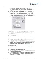
of the encoder (0-360° with single turn encoders).The pre scale offset must be adjusted to
avoid any 7FFFFFF to 8000000 overflow within the used range of the encoder. The value is
added to the encoder reading, neglecting an overfly eventually occurring. Thus, the offset
implements a 360° turnaround automatically.The pre scale offset may be computed and set
manually or by assistance of the ACU's automatic calibration function as described below.
Post scale offset --- The post scale calibration offset is added to the position value before
the angle value is displayed, but after the scaling is applied. The post scale offset is defined
in degrees of AZ/EL/POL.The ACU provides a function to calculate and set both, the pre-
scale and the post-scale offset from a known pointing:
1. Set the calibration scale / gear ratio for the axis (this calibration parameter is described
with the next paragraph).
2. Set the soft limits of the axis to preliminary values. In most cases this needs not to be
very accurate, the ACU needs this information to calculate the pre-scale offset to shift
the encoder overflow outside the used range.
3. Optimize the satellite pointing for the reception from a satellite for which the azimuth and
elevation values are known.
4. Click to the 'calc' label beside the calibration offset.
5. Enter the known pointing angle for the satellite and click to submit.
6. The ACU calculates and sets the calibration offsets to a value so that the actual pointing
is displayed as the angle you entered.
For the azimuth axis there is another offset which also is taken into account, the 'Antenna course'.
This value is provided for mobile applications where a compass reading has to be included into
the azimuth value.
Calibration scale --- Normally the ACU assumes that the full range of a position sensor
corresponds 360°. If you are using a multiturn position sensor or if the position sensor is
mounted to the shaft of a gear rather than to the antenna axis directly, the position sensor
reading must be scaled. The displayed angle is computed as follows:displayed-value = ((raw-
pre-scale-offs) * scale) + pos-scale-offsMathematically a scale value of 1.0 disables
the scaling. Beside this, the ACU also accepts the special value 0 to disable scaling at all. If
you set 1.0, the ACU performs the scaling with this factor. With the value 0 the scaling is
skipped completely, including the conversion of the reading to floating point. This ensures,
that the full accuracy is retained in cases where no scaling is necessary.
Sense invert --- With this parameter you easily can reverse the sense of a position sensor.
The sense should be as follows:
Azimuth: The antenna looks more to the west for larger values.
Elevation: Larger values mean higher elevation.
Polarization: The feed turns clockwise (when looking through the antenna to the
satellite) for increasing values. When operated on the southern hemisphere, the
polarization sense must be set the other way round.
Motor driver type --- The ACU knows two different configuration modes to control a motor
driver. They are called DIR-START and DUAL-START. In DIR-START mode, the FWD signal
switches the motor on/off, the REV signal controls the motor direction. This is the
configuration many frequency inverters use. In DUAL-START mode, the FWD signal
switches the motor on in forward direction, REV activates the motor in reverse direction. This
configuration mode is convenient to control a motor with relays. Beside the modes DIR-
START and DUAL-START you may set the motor driver type to NONE which prevents the
ACU from controlling the motor at all.
(C) 2022, SatService GmbH
www.satnms.com
ACU-ODM-UM-2209 Page 36/73


