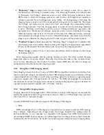
4.
"Balancing" stage
is entered when the maximum cell voltage is more than or equal to
the "Maximum Cell Voltage" parameter value. The balancing threshold is by default equal
to "Maximum Cell Voltage” parameter value as well. When balancing condition is active
BMS starts to divert the charging current for each battery cell through shunt resistors in
attempt to prevent the cell voltages from rising further. At the beginning of this stage the
charging device is kept on until the maximum cell voltage starts to exceed the ”Maximum
Cell Voltage” parameter value by more than 10 mV, even though the corresponding battery
cell is being balanced. Then the charging device is turned off and the balancing threshold
is set to "Minimum Cell Voltage" plus the value of ”Voltage Disbalance” parameter (but
not higher than ”Maximum Cell Voltage” parameter value) in order to dissipate the energy
difference between cells as heat. At the end of this phase the difference between minimum
and maximum cell voltages is lower than the ”Allowed Disbalance” parameter value, then this
stage is over, otherwise the charging device is turned on again and this process repeats.
5.
"Finished" stage
is entered whenever the "Balancing Stage" is completed. It indicates that
the charging process is complete, therefore during this stage the charging device, regardless if
its type, is disconnected from the battery pack by opening the charging contactor.
6.
"Error" stage
is entered if one of the several pre-defined critical conditions are met during
he charging process.
Each charging stage persists until its entering condition is valid. The order in which charging
stages take place is not strictly defined. Naturally, they follow the order as they are listed above,
but it can vary depending on the situation. For safety reasons BMS does not allow to change any
configuration parameters during the charging process.
3.3.1
Using Non-CAN charging device
Basic charging devices that do not have any EMUS BMS compatible interface for controlling their
output current and voltage (also referred to as Non-CAN charging devices) are controlled by utilizing
a special algorithm to turn them on an off using a switching device that is driven by a general purpose
output pin mapped with ”Charger Enable” pin function. The BMS acknowledges the connection
and disconnection of such charging device whenever a corresponding high/low signal is detected on
a general purpose input pin mapped with ”AC Sense” function;
3.3.2
Using CAN charging device
Charging devices that are equipped with a CAN interface (or simply CAN chargers) are controlled by
sending the requested output voltage and current values to them in a CAN message using a protocol
that is specific to a particular charger.
Currently EMUS BMS mini officially supports the following CAN chargers:
•
Elcon
BMS acknowledges that a CAN charger is connected when it receives a particular CAN message
from a charger. Depending on the charger model, the charger transmits this message either by
itself (periodically), or as a response to a requested CAN message from BMS. Disconnection is
acknowledged if BMS does not receive any CAN message from the charger for more than 15 seconds.
Consequently, the "Pin Function: AC Sense" has no meaning when using this type of charging device.
16


