TMCM-1310 TMCL Firmware V1.11 Manual (Rev. 1.16 / 2014-MAR-19)
79
www.trinamic.com
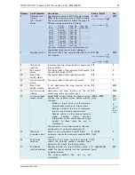
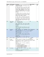
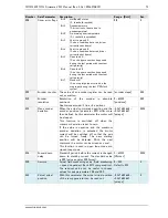
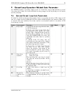
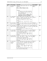
Number Axis parameter
Description
Units / Default
Acc.
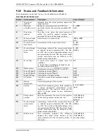
212
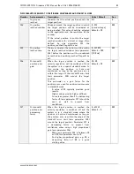
Max. encoder
deviation
When the actual commanded position and
the encoder position (parameter 209) differ
more than defined by this parameter the
motor will be stopped.
This function is switched off when the
maximum deviation is set to zero.
If the value is negative and the maximum
encoder deviation is exceeded, the motor
current will be switched off so that the axis
can be turned freely. The new starting
position will be detected. With the next
command the motor can be driven as usual.
This function is used in open loop mode and
closed loop mode.
−2.147.483.648…
+2.147.483.647
[µsteps]
RWE
9.2
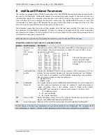
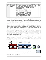
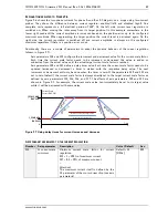
General Structure of the Closed Loop System
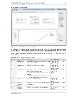
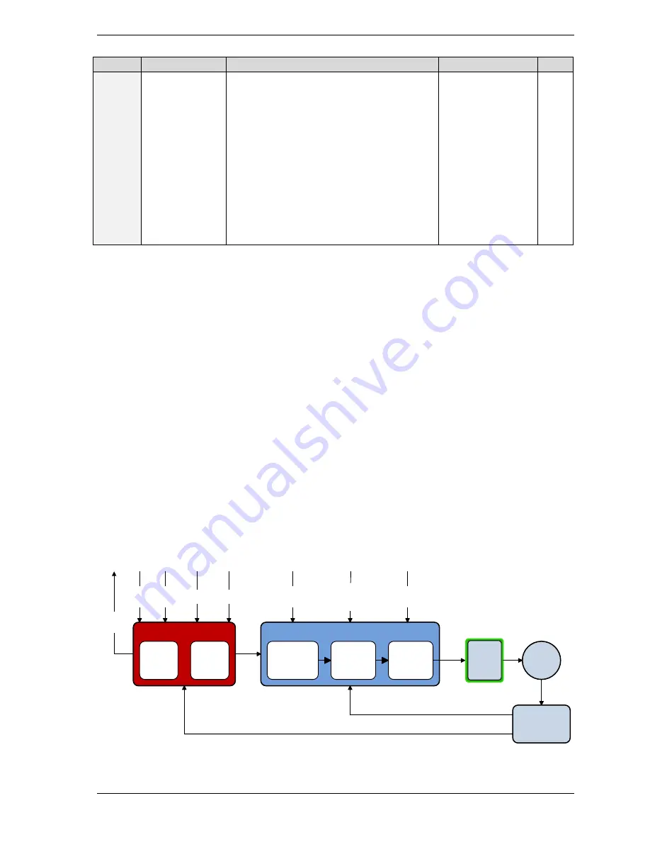
The general structure of the closed loop system of the TMCM-1310 focuses on ease of use. Basically, the
stepper motor will be controlled similar to open loop mode. Nevertheless, extended functionality is
provided for control of position, velocity, and current amplitude. The structure consists of three major
blocks: a ramp generator, a torque control block, and the driver plus actuator. The structure is shown in
Figure 9.1.
The
ramp generator
is primarily used for ramp calculation, velocity control (velocity mode) and position
control (position mode). When using the TMCM-1310 in open loop, this block behaves just like a typical
ramp generator and the stepper motor can lose steps if load is too high. In closed loop mode, the ramp
generator provides extended functionality to control position and velocity.
The
torque control
block is used to control commutation angle and current level. Further it provides an
option to compensate back EMF at higher speeds. Current level control can be switched off but closed loop
operation is still possible. When using current level control the current amplitude is dynamically adapted
to the actual load condition and the actual position error accounting for high drive efficiency and low heat
dissipation in the stepper motor. Additionally, the torque control block is used without ramp generator for
position maintenance during motor stand-still.
The
driver block
is realized using the integrated Trinamic TMC262 stepper motor pre-driver and a dedicated
MOSFET stage. The TMC262 powers the stepper motor windings with the commanded current vectors of
the torque control block. The actuator is the stepper motor itself including an encoder for position
feedback. Rigid coupling and good alignment between motor and feedback is required for proper closed
loop operation.
Torque Control
IA / IB
Commutation
Angle Control
Current
Level Control
Parameters
actual velocity / position
Ramp
Parameters
Ramp Generator
target
Velocity
(SAP 2)
actual velociy / position / electrical angle
Commutation
Angle Control
Parameters
target
Position
(SAP 0)
Field
Weakening
Control
Parameters
2-Phase
Motor
Field
Weakening
Current
Level
Control
Flags/
Status/
Errors
Velocity
Control
Position
Control
acceleration
(SAP 5)
Energy
Efficient
Driver
TMC262
TMC262
&
Driver
Stage
Feedback (ABN):
position
velocity
el. angle
Figure 9.1 Closed Loop System Structure

