Reproduction forbidden without Fibocom Wireless Inc. written authorization - All rights reserved.
FIBOCOM MC610 Series Hardware Guide
44/70
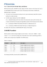
3.8.1.2 Instructions for Module Sleep and Wakeup:
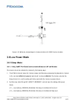
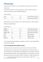
MC610 modules provide a KEYINT for module wakeup. When the module is in the sleep mode, lower or
rise the WAKEUP_IN pin to wake up the module. If the wakeup module function is disabled, the
WAKEUP_IN pin is suspended.
1. The block is not in the sleep mode by default. A non-0 value must be set by the ATS24 command,
and then the module can sleep.
2. x Set the wakeup mode by AT+GTSET="LPMMODE".
x=0 --- interrupt the wakeup. After the module is in the sleep mode, wake up the module by level
conversion. IDLE will be in the sleep mode again after a period of time for wakeup (it is 0 by default);
X=1 --- level wakeup, WAKEUP_IN indicates that sleep is not allowed at low level;
X=2 --- level wakeup, WAKEUP_IN indicates that sleep is not allowed at high level.
For details of the sleep mode, see
FIBOCOM MC610 Series AT Commands
.
3.9 ADC Function
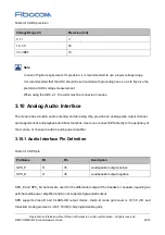
MC610 provides 4-channel analog-to-digital converter interface, 11 bits. Use AT + MMAD = <Index>,
<index> = 1, 2, 3, 4, and then the voltage value of each ADC can be read, the default range of ADC is
0-VBAT, and the voltage range is adjustable in the OPEN version.
Table 3-17 ADC pins
Pin Name
I/O
Pin
Description
ADC0
I
64
Analog-to-digital converter interface 1
ADC1
I
59
Analog-to-digital converter interface 2
ADC2
I
108
Analog-to-digital converter interface 3
ADC3
I
111
Analog-to-digital converter interface 4
The following is the ADC precision tested on ADP-MC610-LA:

