57 / 71
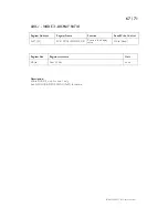
LCD MODE1 TEXT
Register Address Register
Name Function Read/Write
Control
0x29 (41)
LCDMODE1TEXT
Mode’s 1 display text
Write (Read)
Register Size Register
structure Unit
80 Byte (only)
80 x Char (Unsigned Byte)
none
Description:
When register
MODE=
1, the text defined with
LCDMODE1TEXT
is displayed on the LCD.
The first line is static(text), while the 3 other lines are dedicated to one axis each (line2=axis1,
line3=axis2, line4=axis3). A line has ALWAYS 20 characters.
Each axis position is multiplied with
AXIS(i)MODE(j)DISPLAYRATIO
, (i,j=1,2,3) depending of the mode
used. The integer result can be displayed on the corresponding line on the LCD.
8 digits and 1 more character for the sign are displayable. So the value range is -16’777’216 to16’777’215.
With bigger values, “MAX” is displayed, and with lower values “MIN” is displayed. To define the place of
each character, put “#” in the text. If not all 9 “#” are defined the least significant characters are skipped.
For example: if -07‘654’321 is the result of a multiplication the 2 LSB are useless, only 7 # will shows the
good result: -076543.
The 2 last characters of the line are always overwritten with the status of the axis, so do not use them.
For ASCII table compatibility, see the LCD datasheet pattern generator to know which characters are
displayable.
Example:
Byte
Id
01234567890123456789
Byte range
0 … 19
“Module Mode 1 “
20 … 39
“Axis1 ####.### um __“
40 … 59
“2 ###’###’### pls __“
60 … 79
“3####mm ###um (#) __“
WARNING: Be sure to send always 20 characters for each line (4x), for a total of 80 characters (bytes)
to this register.
FMod-IPAXESCTRL User Manual v.1.1


