Options
Ethernet/IP (Communication Option 2)
61
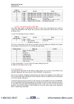
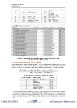
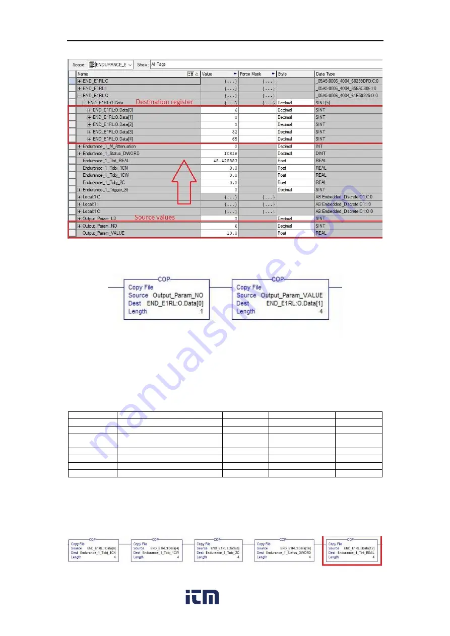
Figure 44: Controller tags: Parameter number and value and their destination registers
in the device
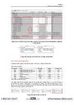
Figure 45: Sample instruction for sending output data
8.8.3.3. Pyrometer Input Data
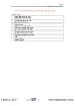
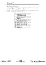
The Ethernet/IP device Input data length is 23 bytes, transferred as SINT.
Input data structure:
Attribute ID
Name
Data type*
Length
Access rule
0x01
Object temperature two color
REAL
4 Byte
Get
0x02
Object temperature one color wide
REAL
4 Byte
Get
0x03
Object temperature one color
narrow
REAL
4 Byte
Get
0x04
Internal temperature
REAL
4 Byte
Get
0x05
Status
DWORD
4 Byte
Get
0x06
Trigger state
USINT
1 Byte
Get
0x07
Measured attenuation
UINT
2 Byte
Get
*target data type after conversion
The data must be processed (copied) into especially created tags in a correct format in
accordance to
column “Data type”. For example, to obtain the internal temperature of the
device, one should create a REAL tag and an instruction copying 4 bytes of the device’s input
data into this tag, beginning with byte 12.
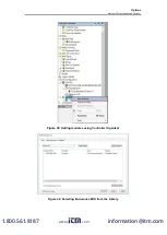
Figure 46: Input data conversion
www.
.com
information@itm.com
1.800.561.8187


