Section 50
00-02-1031
2019-08-07
- 24 -
Control Loop Setup Screen
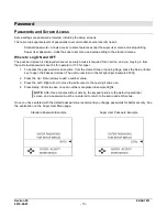
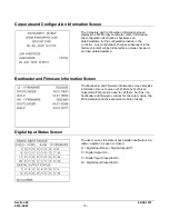
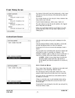
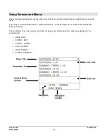
Users may view and edit up to eight (8) configured control loops. The settings on this page will differ depending
on the type of control configured for the system. The control loops all operate on the principle of a 0-100%
calculated output with special considerations for the Digital loop types. Four control loop types are possible.
a) Analog and Digital types use a closed loop PID calculation to calculate the output value, in which a
process variable is maintained at a desired setpoint with the PID generating a 0-100% corrective action to
the process. The ultimate goal of the PID is to reduce the error to zero effectively maintaining the control
setpoint (e.g. speed, load, pressure). PID calculations attempt to model the process being controlled by
allowing tuning for the dynamics of the process based on the present (Proportional), past (Integral) and
future (Derivative) error of the loop. The controller uses the parallel form of the PID equation as follows:
% Output = Kp(Error) + Ki∫(Error)dt + Kd×dError∕dt
b) 2 Pulsed Digital type uses a closed loop pulse equation that calculates the On time for either the increase
or decrease digital output based on the control error.
% Output = (Error x Kp) + 50%
The ultimate goal of the loop is to reduce the error to zero effectively maintaining the control setpoint (e.g.
speed, load, pressure). The control algorithm is centered at 50% output. At 50% output, neither digital
output is on. The control loop will either add to 50% or subtract from 50% to pulse the increase or the
decrease outputs. Larger deviation from 50% will result in longer output pulses.
c) 4-Step Load turns on 4 digital outputs in a 4-step staggered loading scheme with time delays in between
the loading steps. The ultimate goal of the loop is to reduce the error to zero while maintaining the control
setpoint (e.g. speed, load, pressure). The control loop will turn on the outputs in succession, and the 0-
100% control value will step up from 0 to 20%, 40%, 60% and 80% as the time delays expire. If the
deadband is reached, the time delays will reset, and no change in control will occur.
d) Open Loop calculates an analog output value using a linear scaling based on a feedback input. In this
case, there is no closed feedback and no setpoint to maintain. There are 2 coordinates specified in
engineering units for the process being controlled, one for minimum % output and one for maximum %
output. A linear scaling function will be applied using these 2 values to range the output between the
specified minimum and maximum % settings.
e) Common setpoints to Analog/Digital, 2 Pulsed Digital and 4-Step Load loop types. Open Loop Ramp
loop type shares only those setpoints marked with (*).
1. Auto/Manual Mode*: Set the loop to Auto to enable the control. Set to Manual to allow user entry for
the control output as a 0.00-100.00% value.
2. Setpoint: Assign the desired value that is to be maintained by the loop. Depending on configuration this
may be a variable setpoint based on analog input, not user editable from the display.
3. Deadband: Assign a value around the setpoint during which the loop will not take any
corrective action.
4. Minimum Output*: Set the minimum limit on the calculated value during auto control
5. Maximum Output*: Set the maximum limit on the calculated value during auto control.
6.
Loop Update time: Loop calculation frequency. This time should be set no shorter than the update rate
for the feedback reading.

