BL652 Development Kit
User Guide
Embedded Wireless Solutions Support Center:
http://ews-support.lairdtech.com
www.lairdtech.com/bluetooth
27
© Copyright 2016 Laird. All Rights Reserved
Americas: +1-800-492-2320
Europe: +44-1628-858-940
Hong Kong: +852 2923 0610
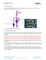
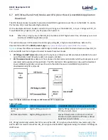
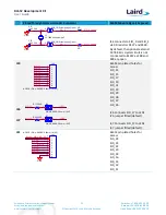
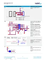
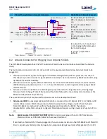
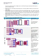
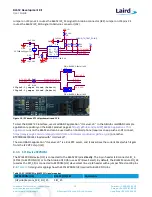
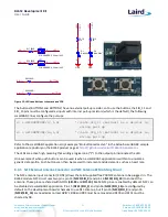
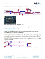
Figure 11: Analog Buffer schematic and PCB
The selection jumper on J6 connects either Temperature Sensor analog output or the output of the Arduino
analog input buffer to SIO_3. By default, no jumper is fitted in J6 in either position. To select the Arduino analog
input buffer to SIO_3, fit the jumper on J7 to short pins 2-3.
8.3
Additional Peripherals/Sensors
The BL652 development board provides for simple and hassle free connectivity to a wide range of sensors, but
also includes several on-board sensors and options to enable a developer to test functionality straight out of the
box.
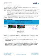
In the smartBASIC application code written to use sensors on the development board (including the
Temperature sensor (U1) – analog output, Analog Input Buffer (U3) – analog output, SPI EEPROM (U2), I2C RTC
chip (U16), LED1(D1), LED2(D2) Button1(SW1), and Button2(SW2)) the SIO pins direction and type must be set in
the smartBASIC application to override the defaults in the BL652 firmware.
For more information on these sample applications, see GitHub smartBASIC sample applications repository on
the BL652 product page at
https://github.com/LairdCP/BL652-Applications
8.3.1
Temperature Sensor
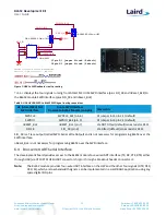
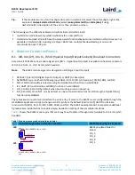
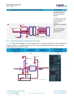
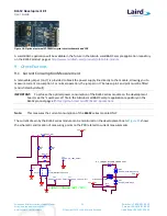
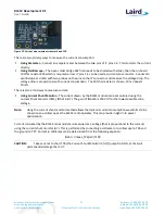
The temperature sensor (U1) by default is connected to the BL652 module as jumper on J6 pin 2-1, bridges
TEMP_SENS and SIO_3.
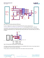
Figure 12: Temperature sensor schematic and PCB
C2
0.1uF,16V
Analog output temp sensor
V+ 2.4V-3.6V
C3
0.1uF,16V
VCC_3V3
Temp_Sens
GND
GND
GND
GND
R5
NOPOP (4.7K)
U1
2.4V,10uA,-55dC~+130dC
V+
4
GND
5
Vo
3
GND
2
NC
1
R4
470R,1%


