13.2
Activating analog triggered AT command
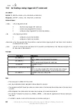
AT+ADCAT
Syntax:
AT+ADCAT=<mode>(,<dir>,<threshold>,<command>)
Response:
+ADCAT: <mode>,<dir>,<threshold>,<command>
Defined Values:
<mode>
is the configuration mode:
0
disable analog triggered AT command,
1
enable analog triggered AT command,
2
configure analog triggered AT command parameters.
<dir>
is the triggering condition:
0
configure as low-to-high condition,
1
configure as high-to-low condition.
<threshold> is the time required, after the condition is reached, before triggering the AT command. Unit is hundred
of millisecond from 0 to 50.
<cmd>
is the AT command to be executed when the condition and threshold are met. Maximum length of the
AT command is 128 characters.
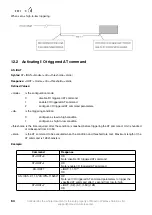
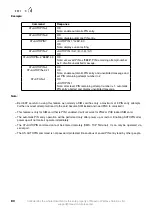
Example:
Command
Response
AT+ADCAT=0
OK
Note: disable analog triggered AT command.
AT+ADCAT=1
OK
Note: enable analog triggered AT command.
AT+ADCAT?
+ADCAT: 1,1,10,""
OK
AT+ADCAT=2,1,10,"AT+IPR=115200"
OK
Note: set analog triggered AT command parameters to trigger
the specified AT command after 1 second from low-to-high.
AT+ADCAT=?
+ADCAT: (0-2),(0-1),(1-50),(128)
OK
Note:
–
The analog port is limited to 5V maximum.
–
Use only cable/metal contact designed for Molex MicroFit connector.
–
The application will NOT check the command <cmd> entered. It will execute the command even if the command
is invalid.
–
When triggered, the command will not output any response to the external serial port.
–
Do not enter "interactive" command (i.e
+CMGS
,
+WDWL
,...), otherwise the application will be stuck waiting for
user input.
–
If +ADCAT is enable, no other AT command can control the analog port.
68
Confidential, the whole document is the sole property of Maestro Wireless Solutions ltd.
support@maestro-wireless.com


