background image

MVI69L-MBS ♦ Platform 

Reference 

Modbus Serial Lite Communication Module  

User Manual 


ProSoft Technology, Inc. 

Page 105 of 130 


In this example, the master's Modbus packet contains the data byte and data 
word counts that have NOT been doubled from the amount specified by Reg 
Count due to the Float Flag set to N. The slave looks for the byte count in the 
data packet to know the length of the data to read from the wire. Because of 
insufficient byte count, some slaves read only half the data from the master's 
transmission. Other slaves read all 8 bytes in this example because they know 
where in the packet the data starts and ignore the byte count parameter inside 
the Modbus packet. 

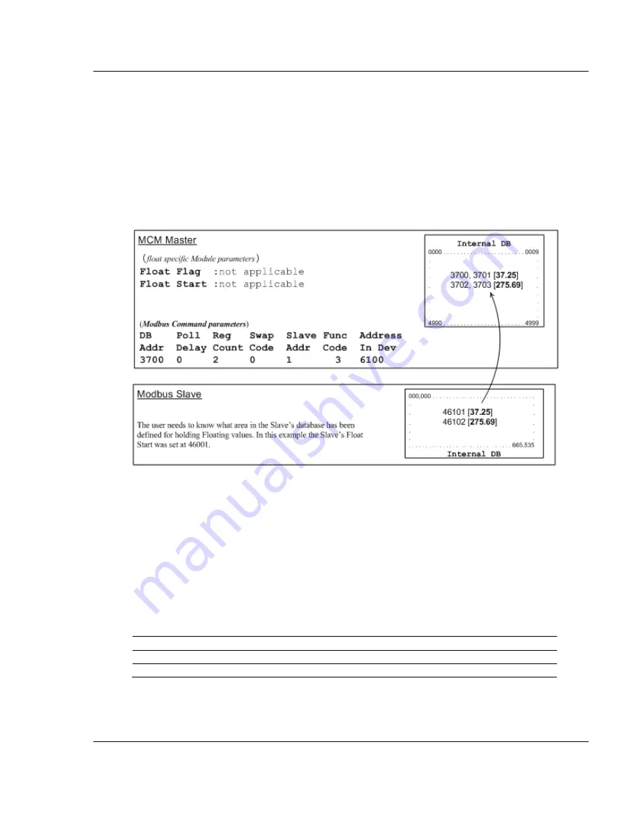
Example #3: Master issuing Modbus command with FC 3 to transfer Float data from slave. 


Float Flag: 

Not applicable with Modbus Function Code 3. 

Float Start: 

Not applicable with Modbus Function Code 3. 

DB Addr 

- Tells the master where in its data memory to store the data obtained 

from the slave. 

Reg Count 

- Tells the master how many registers to request from the slave. 

Swap Code 

- same as above. 

Func Code

 - Tells the master to read the register values from the slave. FC3. 

Addr in Dev 

- Tells the master where in the slave's database to obtain the data.  

In the above example, the master's Modbus command to transmit inside the 
Modbus packet is as follows. 


Slave Address  Function Code  Address in Device  Reg Count 

DEC 

01 

6100 

HEX 

01 

03 

17 D4 

00 02 

In the above example the (Enron/Daniel supporting) slave's Modbus command to 
transmit inside the Modbus packet is as follows. 

Summary of Contents for CompactLogix MVI69L-MBS

Page 1: ...MVI69L MBS CompactLogix Platform Modbus Serial Lite Communication Module May 21 2020 USER MANUAL...

Page 2: ...subsidiaries shall be responsible or liable for misuse of the information contained herein Information in this document including illustrations specifications and dimensions may contain technical ina...

Page 3: ...put I O wiring must be in accordance with the authority having jurisdiction A Warning Explosion Hazard When in hazardous locations turn off power before replacing or wiring modules B Warning Explosion...

Page 4: ...nd Exporting the L5X File 25 2 4 Creating a New RSLogix 5000 Project 27 2 5 Importing the Add On Instruction 28 2 6 Adding Multiple Modules in the Rack Optional 32 2 6 1 Adding an Additional Module in...

Page 5: ...the Module s Ethernet Port 76 6 3 1 Setting Up a Temporary IP Address 77 6 4 Using the Diagnostics Menu in PCB 79 6 4 1 Diagnostics Menu 81 6 4 2 Monitoring General Information 81 6 4 3 Monitoring Ne...

Page 6: ...File Block 9001 or 9001 113 7 4 10 Get General Module Status Data Block 9250 114 7 4 11 Set Port and Command Active Bits Block 9500 115 7 4 12 Get Port and Command Active Bits Block 9501 116 7 4 13 Pa...

Page 7: ...Modbus and CompactLogix devices to a power source and to the MVI69L MBS s application port s 1 1 System Requirements The MVI69L MBS requires the following minimum hardware and software components Roc...

Page 8: ...logy Other third party applications may have different minimum requirements Refer to the documentation for any third party applications for system requirements 1 2 Deployment Checklist Before you begi...

Page 9: ...erify that all of the following items are present Qty Part Name Part Number Part Description 1 MVI69L MBS MVI69L MBS Modbus Serial Lite Communication Module 1 Adapter Cable Cable 14 RJ45 to DB9 Male A...

Page 10: ...ust set the jumpers to the correct position The following diagram describes the jumper settings Note Jumper pin placement on the circuit board may vary The Setup Jumper acts as write protection for th...

Page 11: ...nstalling this or any other electronic devices Failure to follow safety procedures could result in damage to hardware or data or even serious injury or death to personnel Refer to the documentation fo...

Page 12: ...Technology Inc 1 Align the module using the upper and lower tongue and groove slots with the adjacent module and slide forward in the direction of the arrow 2 Move the module back along the tongue and...

Page 13: ...nication Module User Manual ProSoft Technology Inc Page 13 of 130 3 Push the module s bus lever back slightly to clear the positioning tab and move it firmly to the left until it clicks Ensure that it...

Page 14: ...Platform User Manual Modbus Serial Lite Communication Module Page 14 of 130 ProSoft Technology Inc 5 Press the DIN rail mounting area of the controller against the DIN rail The latches momentarily ope...

Page 15: ...thod if you have RSLogix version 14 or earlier 3 Create an Add On Instruction file using ProSoft Configuration Builder PCB and export the Add On Instruction to an RSLogix 5000 compatible file L5X file...

Page 16: ...Profile 1 Download the AOP file MVI69x_RevX X_AOP zip from the product webpage found at www prosoft technology com and extract the files from the zip archive Make sure you have shut down RSLogix 5000...

Page 17: ...ft Technology Inc Page 17 of 130 4 Click FINISH when complete The AOP is now installed in RSLogix 5000 You do not need to reboot the PC Using an Add On Profile 1 In RSLogix 5000 expand the I O CONFIGU...

Page 18: ...odule Page 18 of 130 ProSoft Technology Inc This opens the Select Module Type dialog box In the Module Type Vendor Filters area uncheck all boxes except the PROSOFT TECHNOLOGY box A list of ProSoft Te...

Page 19: ...anual ProSoft Technology Inc Page 19 of 130 3 A New Module dialog box opens Edit the NAME and SLOT for the module and click OK Note This module uses a block transfer size of 240 only Therefore it uses...

Page 20: ...you installed the ProSoft Technology Add On Profile for this module 1 Expand the I O CONFIGURATION folder in the Project tree Right click the appropriate communications bus and choose NEW MODULE This...

Page 21: ...r a description for the module Example ProSoft communication module for Serial Modbus communications Comm Format Select DATA INT Slot Enter the slot number in the rack where the MV69E MBS module is in...

Page 22: ...tains the PCB version number For example PCB_4 3 4 5 0238 EXE Installing PCB from the ProSoft website 1 Open a browser window and navigate to www prosoft technology com 2 Perform a search for pcb in t...

Page 23: ...ilder PCB and to export the L5X file for the project 2 3 1 Setting Up the Project in PCB To begin start PROSOFT CONFIGURATION BUILDER PCB The PCB window consists of a tree view on the left and an info...

Page 24: ...ick DEFAULT MODULE and then click CHOOSE MODULE TYPE This opens the Choose Module Type dialog box 2 In the Product Line Filter area of the dialog box click MVI69 In the Select Module Type dropdown lis...

Page 25: ...the L5X file that is exported Before exporting the L5X file to the PC Laptop check the Block Transfer Size and Slot Number parameters 1 Expand the MVI69L MBS icon by clicking the symbol beside it Sim...

Page 26: ...nual Modbus Serial Lite Communication Module Page 26 of 130 ProSoft Technology Inc 4 Right click the MVI69L MBS icon in the project tree and then click EXPORT AOI FILE 5 Save the L5X file to the PC La...

Page 27: ...nual ProSoft Technology Inc Page 27 of 130 2 4 Creating a New RSLogix 5000 Project 1 Click the FILE menu and then choose NEW 2 Select your CompactLogix controller model 3 Select REVISION 16 or newer 4...

Page 28: ...TASK folder 3 Expand the MAINPROGRAM folder The MAINROUTINE contains rungs of logic The very last rung in this routine is blank This is where you can import the Add On Instruction Note You can place t...

Page 29: ...al Lite Communication Module User Manual ProSoft Technology Inc Page 29 of 130 5 Select the L5X file that you exported from PCB This opens the Import Configuration dialog box Click TAGS under MAINROUT...

Page 30: ...If the module is not located in the default slot or is in a remote rack edit the connection input and output variables that define the path to the module in the FINAL NAME column NAME column for RSLo...

Page 31: ...cation Module User Manual ProSoft Technology Inc Page 31 of 130 When the import is complete the new Add On Instruction rung is present The procedure also imports new user defined data types data objec...

Page 32: ...le configuration as an L5X file 3 Add a new MVI69L MBS to the RSLogix 5000 project 4 Import the L5X file into RSLogix 5000 for the new module as an Add On Instruction 2 6 1 Adding an Additional Module...

Page 33: ...lt name on a duplicate module appends a number to the end such as MVI69L MBS_000 MVI69L MBS_001 etc 6 You can rename the module by right clicking the module and choosing Rename 7 Configure the module...

Page 34: ...nal module to the rack is similar to installing a new module however the name of the module must be unique 1 Start RSLogix 5000 and open the project 2 In RSLogix 5000 locate the I O CONFIGURATION fold...

Page 35: ...of 130 4 The New Module dialog box appears Enter a unique name for the new module and confirm the slot number of the new module 5 Click OK The new module is now visible 6 You must also import the Add...

Page 36: ...g the Module to RSLogix MVI69L MBS Platform User Manual Modbus Serial Lite Communication Module Page 36 of 130 ProSoft Technology Inc 7 Right click an empty rung in the routine and then choose IMPORT...

Page 37: ...s Serial Lite Communication Module User Manual ProSoft Technology Inc Page 37 of 130 8 Select the L5X file you created and exported for the new module and click IMPORT Recall that the new L5X file has...

Page 38: ...bus Serial Lite Communication Module Page 38 of 130 ProSoft Technology Inc 9 This opens the IMPORT CONFIGURATION dialog box Click TAGS to show the controller tags in the AOI You must edit the FINAL NA...

Page 39: ...e in the corresponding slot number The default values are Local 1 I and Local 1 O You must edit these values if the card is placed in a slot location other than slot 1 Local 1 x means the card is loca...

Page 40: ...MVI69L MBS Platform User Manual Modbus Serial Lite Communication Module Page 40 of 130 ProSoft Technology Inc 11 Click OK The setup procedure is now complete Save the project It is ready to download t...

Page 41: ...boots up it requests the processor to send the configuration over the backplane in special Configuration Blocks See Adding the Module to RSLogix page 15 for the procedures to create a new PCB project...

Page 42: ...an Edit dialog box To edit a parameter select the parameter in the left pane and make your changes in the right pane Note Depending on the parameter you must enter text or a valid number or select fr...

Page 43: ...uring the MVI69L MBS Using PCB Modbus Serial Lite Communication Module User Manual ProSoft Technology Inc Page 43 of 130 6 To add a row to the table click ADD ROW 7 To edit the row click EDIT ROW This...

Page 44: ...y the module and the configuration file Backplane Fail Count 0 to 65535 Specifies the number of consecutive backplane transfer failures that can occur before communications are halted Error Status Blo...

Page 45: ...r 2 Sets the number of stop bits that signal the end of a character in the data stream For most applications use one stop bit For slower devices that require more time to re synchronize use two stop b...

Page 46: ...in your application then set this parameter to NO which is the default setting You also need to set the Float Start and Float Offset parameters to appropriate values whenever the Float Flag parameter...

Page 47: ...etries of a command as retries are issued when a command failure is recognized Error Delay Counter 0 to 60000 Specifies the number of poll attempts to be skipped before trying to re establish communic...

Page 48: ...e offset address into the internal Modbus database for network requests for Modbus function 2 commands For example if you set the value to 150 an address request of 0 returns the value at register 150...

Page 49: ...since the command was last issued the command is not executed You can use this feature to optimize network performance The MBS Modbus Master and Slave communication drivers support several data read...

Page 50: ...fore if a value of 100 is entered the command executes no more frequently than every 10 seconds When the command reaches the top of the command queue and 10 seconds has not elapsed it is skipped until...

Page 51: ...he value entered here does not need to include the Modbus Prefix addressing scheme Also this value is an offset of the zero based Modbus addressing scheme Example Using a Modbus Function Code 3 to rea...

Page 52: ...ommunication Module Page 52 of 130 ProSoft Technology Inc 3 3 Downloading the Configuration File to the Processor 1 In the ProSoft Configuration Builder tree view right click the module icon and choos...

Page 53: ...anual ProSoft Technology Inc Page 53 of 130 3 Browse to and then highlight the CompactLogix processor and click OK 4 Notice the CIPConnect path has been updated in the Download Configuration File dial...

Page 54: ...file to the processor Following the download process the module reboots 6 After rebooting the ladder logic sends the configuration data from the processor to the module When that is complete the modu...

Page 55: ...Manual ProSoft Technology Inc Page 55 of 130 2 In the Upload Configuration File dialog box the CIPConnect path should already be constructed if you have previously downloaded the configuration file f...

Page 56: ...unication Module Page 56 of 130 ProSoft Technology Inc 3 Click TEST CONNECTION to verify the path is active and can successfully connect to the processor 4 When ready click UPLOAD When upload is compl...

Page 57: ...dule configuration the module begins communicating with other devices on the Modbus network depending on the Modbus configuration of the module 4 2 Backplane Data Transfer The MVI69L MBS communicates...

Page 58: ...database This database is defined as virtual MBS data tables with addresses from 0 to 239 each 4 3 Normal Data Transfer Normal data transfer includes the paging of the user data found in the module s...

Page 59: ...ackplane between the module and the processor The Write Block ID associated with the block requests data from the processor Under normal program operation the module sequentially sends read blocks and...

Page 60: ...stored in the database to addresses different from addresses requested in the received messages 2 A Modbus Master device such as a Modicon PLC or an HMI application issues a read or write command to t...

Page 61: ...returned to the Slave driver so it can build a response message c In Pass Through mode if the Slave driver receives a write request it does not send the data directly to the module s internal database...

Page 62: ...f the module Step Description 1 Upon module boot up the Master driver obtains configuration data from the MBS controller tags The configuration data retrieved includes port configuration and the Maste...

Page 63: ...bits for Function Codes 1 2 or 15 Note 125 words is the maximum count allowed by the Modbus protocol Some field devices may support less than the full 125 words Check with the device manufacturer for...

Page 64: ...ections of controller tags called controller tag structures A controller tag structure can contain any combination of Individual controller tags Controller tag arrays Lower level controller tag struct...

Page 65: ...TYPE column displays the data types used to declare each controller tag controller tag array or controller tag structure Individual controller tags are declared with basic data types such as INT and...

Page 66: ...ure MBS There are five UDTs one level below MBSMODULEDEF These lower level UDTs were used to create the MBS CONFIG MBS DATA MBS CONTROL MBS STATUS and MBS UTIL controller tag structures Click the sign...

Page 67: ...ique CRC to protect data integrity Any change to the configuration parameters directly in this array will not match the calculated CRC Tag Name Description MBS CONFIG FileData This parameter contains...

Page 68: ...Number 1 Port number to be associated with command CommandIndex x 0 or 1 Command Index of port command x to be enabled Up to 6 command indexes can be populated at a time MBS CONTROL EventCmd_DBData Th...

Page 69: ...es to be sent to the slave EventCmdStatusReturned Command status Port1Status Port 1 Status array Port1Status Status Status code See Communication Error Codes page 84 Port1Status LastError Last error c...

Page 70: ...cond MBS CONTROL GetStatus This tag allows the processor to retrieve status from the module Tag Name Range Description GetStatus 0 or 1 Triggers status retrieval from the module 0 Disable 1 Enable MBS...

Page 71: ...n port 1 Port1Stats PortErrSent Total number of message errors sent out of port 1 Port1Stats PortErrRec Total number of message errors received on port 1 Port1Stats CurrErr Not used Port1Stats LastErr...

Page 72: ...Offset in configuration file to use as a starting point for copying over configuration data ConnectionInputSize Holds size of the Connection Input array 240 BlockTransferSize Size of the backplane tra...

Page 73: ...s status You can view status data contained in the module through the Ethernet port using the troubleshooting and diagnostic capabilities of ProSoft Configuration Builder PCB You can transfer status d...

Page 74: ...r is being configured If the LED remains red for over 10 seconds the program has probably halted During module configuration the OK LED is red and the BP ACT LED is on If the APP BP ACT and OK LEDs bl...

Page 75: ...at all modules in the rack are correctly configured Module Errors Problem description Steps to take BP ACT LED not present on MVI56E modules remains OFF or blinks slowly MVI69 modules with scrolling L...

Page 76: ...echnology Inc 6 3 Connecting the PC to the Module s Ethernet Port With the module securely mounted connect one end of the Ethernet cable to the ETH1 Port and the other end to an Ethernet hub or switch...

Page 77: ...ble to locate the modules To use ProSoft Configuration Builder arrange the Ethernet connection so that there is no router layer 3 switch between the computer and the module OR reconfigure the router l...

Page 78: ...unused IP within your subnet and then click OK Important The temporary IP address is only valid until the next time the module is initialized For information on how to set the module s permanent IP a...

Page 79: ...menus for debugging and troubleshooting To connect to the module s Configuration Debug Ethernet port 1 In the tree view in ProSoft Configuration Builder right click the MVI69L MBS and then choose DIAG...

Page 80: ...oft Technology Inc 3 In the Ethernet field of the Connection Setup dialog box enter the current IP address whether it is temporary or permanent Click TEST CONNECTION to verify that the module is acces...

Page 81: ...ostics Menu In the Diagnostics window in ProSoft Configuration Builder the Diagnostics menu is available through the Ethernet configuration port The menu is arranged as a tree structure 6 4 2 Monitori...

Page 82: ...Configuration Information In the Diagnostics window in Prosoft Configuration Builder click NETWORK and then click CONFIG to view the Ethernet network configuration information 6 4 4 Monitoring Backpl...

Page 83: ...on The MODBUS PORT 1 menu includes the following submenus Configuration Status General status for the port Master Commands Used when port is configured as a Modbus master Slave Status List Status of e...

Page 84: ...that is not listed below check with the documentation of the Modbus device s on the module s application ports Modbus devices can produce device specific error codes 6 5 1 Standard MODBUS Protocol Exc...

Page 85: ...ebpage The module s internal web server provides access to module version and status information as well as the ability to set the date and time reboot the module and download firmware upgrade to the...

Page 86: ...Diagnostics and Troubleshooting MVI69L MBS Platform User Manual Modbus Serial Lite Communication Module Page 86 of 130 ProSoft Technology Inc...

Page 87: ...le between the Modbus network and the CompactLogix backplane The data transfer from the CompactLogix processor is asynchronous from the actions on the Modbus network Databases are user defined and sto...

Page 88: ...solation from backplane Shipped with Unit RJ45 to DB 9M cable for application port 7 1 3 General Specifications Modbus Master Slave Communication Parameters Baud rate 110 to 115K baud Stop bits 1 or 2...

Page 89: ...he processor and Master and Slave devices on Modbus networks 7 2 1 Modbus Master A port configured as a virtual Modbus Master actively issues Modbus commands to other nodes on the Modbus network suppo...

Page 90: ...t contains information required to interface to the Modbus slave device 7 2 4 Read Coil Status Function Code 01 Query This function allows you to obtain the ON OFF status of logic coils Modbus 0x rang...

Page 91: ...l status from sequential scans Node Address Func Code Byte Count Data Coil Status 20 to 27 Data Coil Status 28 to 35 Data Coil Status 36 to 43 Data Coil Status 44 to 51 Data Coil Status 52 to 56 Error...

Page 92: ...ultiples of eight the last characters are filled in with zeros at high order end The quantity of data characters is always specified as a quantity of RTU characters that is the number is the same whet...

Page 93: ...Data Start Registers Low Data Number of Registers High Data Number of Registers Low Error Check Field 2 bytes 0B 03 00 6B 00 03 CRC Response The addressed slave responds with its address and the func...

Page 94: ...ion Code Data Start Point High Data Start Point Low Data Number of Points High Data Number of Points Low Error Check Field 2 bytes 0B 04 00 08 00 01 CRC Response The addressed slave responds with its...

Page 95: ...network The byte values below are in hexadecimal display Node Address Function Code Data Start Bit High Data Start Bit Low Number of Bits High Number of Bits Low Error Check Field 2 bytes 0B 05 00 AC...

Page 96: ...ess zero Broadcast mode all slave controllers load the specified register with the contents specified Note Functions 5 6 15 and 16 are the only messages that are recognized as valid for broadcast Note...

Page 97: ...vices A server device can however be forced into Listen Only Mode in which it monitors the messages on the communications system but not respond to them This can affect the outcome of your application...

Page 98: ...e Any coil that exists within the controller can be forced to either state ON or OFF However because the controller is actively scanning unless the coils are disabled the controller can also alter the...

Page 99: ...t Force Data High 20 to 27 Force Data Low 28 to 29 Error Check Field 2 bytes 0B 0F 00 13 00 0A 02 CD 01 CRC Response The normal response is an echo of the slave address function code starting address...

Page 100: ...is a request to write 2 registers starting at register 40002 in slave 11 Note This is the structure of the message being sent out to the Modbus network The byte values below are in hexadecimal display...

Page 101: ...alues to the module is shown below This instruction moves one floating point value in two 16 bit integer images to MBS DATA WriteData 0 which is an integer tag For multiple floating point values incre...

Page 102: ...01 32 bit REAL TEMP Pump 1 47102 32 bit REAL Pressure Pump 1 47103 32 bit REAL TEMP Pump 2 47104 32 bit REAL Pressure Pump 2 With the module configured as a master you only need to enable these parame...

Page 103: ...e slave Otherwise the master ignores the Float Flag Y and treat data as composed of 1 word 2 bytes Modbus Command parameters DB Addr Tells the master where in its data memory is the beginning of data...

Page 104: ...rom the wire the remaining bytes in the packet as the data the master is sending Example 2 Master issuing Modbus command with FC 16 with Float Flag No to transfer Float data Float Flag N tells the mas...

Page 105: ...odbus packet Example 3 Master issuing Modbus command with FC 3 to transfer Float data from slave Float Flag Not applicable with Modbus Function Code 3 Float Start Not applicable with Modbus Function C...

Page 106: ...1 to 999 Dummy block 0 Read or write data for small data sets 1 to 167 Read or write data 1000 to 1255 Event Command Port 1 3000 to 3001 Port 1 slave polling control 3002 to 3006 Port 1 slave status 5...

Page 107: ...cessor to Module Offset Description 0 Write Block ID 1000 to 1255 for a Port 1 command The last 3 digits of the command specify the slave address to use for the command 1 Internal address in the modul...

Page 108: ...n its next Write block 2 Number of slaves processed in the last request This number should match the value passed in Word 1of the request block 3 to 239 Spare 7 4 3 Slave Polling Enable Blocks 3001 Bl...

Page 109: ...e their polling suspended and disabled Block 3002 to 3006 Request from Processor to Module Offset Description 0 Write Block ID 3002 to 3006 for Port 1 slave polling status request 1 to 239 Spare Block...

Page 110: ...5006 for Port 1 The last digit indicates how many commands are to be placed in the command queue by this block 1 Index in the command list for the first command to be entered into the command queue ap...

Page 111: ...t 2 Modbus function code to use with command 5 6 15 or 16 3 Modbus address in slave device 4 Count value for operation bit count for function 15 1 to 800 points and word count for function 16 1 to 50...

Page 112: ...rite block 2 Event command status for Port 1 0 No message active 1 Waiting to execute command 2 Command complete 3 Error code for last command executed for Port 1 6 to 239 Spare 7 4 8 Get Configuratio...

Page 113: ...ion 0 Read Block ID 9001 or 9001 request for configuration file from processor 1 Write Block ID 9001 or 9001 to be used by the processor in its next Write block 2 to 3 File offset Offset of the first...

Page 114: ...run number value for the currently running software 11 Port 1 Command List Requests Number of requests made from this port to slave devices on the network 12 Port 1 Command List Response Number of sl...

Page 115: ...pare 7 4 11 Set Port and Command Active Bits Block 9500 Block 9500 Set Port and command active bits This block enables and disables Port 1 as well as individual Master commands for a port Block 9500 R...

Page 116: ...nd enable bits for Port 1 commands 0 disabled 1 enabled 23 Spare 24 to 43 Command enable bits for Port 2 commands 0 disabled 1 enabled 44 to 239 Spare 7 4 13 Pass through Formatted Block for Functions...

Page 117: ...odule that the command has been processed and can be cleared from the Pass Through queue Block 9956 Response from Processor to Module Offset Description 0 Write Block ID 9956 1 to 239 Spare 7 4 14 Pas...

Page 118: ...dule to Processor Offset Description 0 Read Block ID 9958 1 Write Block ID 9958 2 Number of word registers in Modbus data set 3 Starting address for Modbus data set 4 to 239 Data The ladder logic is r...

Page 119: ...affected Block 9959 Request from Module to Processor Offset Description 0 Read Block ID 9959 1 Write Block ID 9959 2 Length in words 3 Data address 4 to 28 Modbus Data 29 to 53 Bit mask to use with t...

Page 120: ...hen respond to the pass through control block with an output image write block with the following format Block 9961 Response from Processor to Module Offset Description 0 Write Block ID 9961 1 to 239...

Page 121: ...g Received Time Block 9972 Block 9972 Set Module Time Using Received Time Block This block uses the time information from the processor to set the module time Block 9972 Request from Processor to Modu...

Page 122: ...ck ID 9973 1 to 239 Spare Block 9973 Response from Module to Processor Offset Description 0 Read Block ID 9973 1 Write Block ID To be used by the processor in its next Write block 2 Year 0 9999 3 Mont...

Page 123: ...le performs a warm boot operation The module reconfigures the application port and reset the error and status counters Block 9998 Request from Processor to Module Offset Description 0 Write Block ID 9...

Page 124: ...ule to an Ethernet hub a 10 100 Base T Ethernet switch or directly to a PC The module detects the cable type and uses the appropriate pins to send and receive Ethernet signals Some hubs have one input...

Page 125: ...performance so consider one of these options o Use managed switches to reduce traffic coming to module port o Use CIPconnect for these applications and disconnect the module Ethernet port from the ne...

Page 126: ...of connection is required between the module and a modem or other communication device The Use CTS Line parameter for the port configuration should be set to Y for most modem applications RS 232 Null...

Page 127: ...to connect the module to a computer or field device communication port Note For most null modem connections where hardware handshaking is not required the Use CTS Line parameter should be set to N an...

Page 128: ...epending on the RS 485 network devices used The cable required for this interface is shown below Note Terminating resistors are generally not required on the RS 485 network unless you are experiencing...

Page 129: ...MVI69L MBS Platform Reference Modbus Serial Lite Communication Module User Manual ProSoft Technology Inc Page 129 of 130 7 6 4 DB9 to RJ45 Adaptor Cable 14...

Page 130: ...wn issues North America Corporate Location Europe Middle East Africa Regional Office Phone 1 661 716 5100 info prosoft technology com Languages spoken English Spanish REGIONAL TECH SUPPORT support pro...

Reviews: