COMe-cVR6 – User Guide Rev. 1.5
// 51
7.5.
Dual Staged Watchdog Timer (WTD)
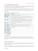
A watchdog timer or (computer operating properly (COP) timer) is a computer hardware or software timer. If there is
a fault condition in the main program, the watchdog triggers a system reset or other corrective actions. The intention
is to bring the system back from the non-responsive state to normal operation.
Possible fault conditions are a hang or neglecting to service the watchdog regularly. Such as writing a “service pulse”
to it, also referred to as “kicking the dog”, “petting the dog”, “feeding the watchdog” or “triggering the watchdog”).
The COMe-cVR6 offers a watchdog that works with two stages that can be programmed independently and used
stage by stage.
Table 62: Dual Stage Watchdog Timer- Time-out Events
Status Events
Definition
0000b No action
The stage is off and will be skipped.
0001b
Reset
A reset restarts the module and starts a new POST and operating system.
0010b NMI
A non-maskable interrupt (NMI) is a computer processor interrupt that cannot be
ignored by standard interrupt masking techniques in the system. It is used typically
to signal attention for non-recoverable hardware errors.
0011b
SMI
A system management interrupt (SMI) makes the processor entering the system
management mode (SMM). As such, specific BIOS code handles the interrupt. The
current BIOS handler for the watchdog SMI currently does nothing. For special
requirements, contact Kontron Support.
0100b
SCI
A system control interrupt (SCI) is a OS-visible interrupt to be handled by the OS
using AML code.
0101b
Delay -> No
action*
Might be necessary when an operating system must be started and the time for the
first trigger pulse must be extended. Only available in the first stage.
1000b
WDT Only
This setting triggers the WDT pin on the baseboard connector (COM Express®
pin B27) only.
1001b
Reset + WDT
1010b
NMI + WDT
1011b
SMI + WDT
1100b
SCI + WDT
1101b
DELAY + WDT
-> No action*
7.5.1.
WDT Signal
Watchdog time-out event (pin B27) on COM Express® connector offers a signal that can be asserted when a
watchdog timer has not been triggered with a set time. The WDT signal is configurable to any of the two stages. After
reset, the signal is automatically deasserted. If deassertion is necessary during runtime, ask Kontron Support for
further help.
7.6.
Real Time Clock (RTC)
The RTC keeps track of the current time accurately. The RTC’s low power consumption means that the RTC can be
powered from an alternate source of power enabling the RTC to continue to keep time while the primary source of
power is off or unavailable.
The RTC battery voltage range is 2.8 V to 3.47 V. A typical RTC voltage is 3 V with a current of >3 μA. If the module is
powered by the mains supply the RTC voltage is generated by on-module regulators to reduce the RTC current draw.


