Name
Type
Initial value
Comment
r/w
1)
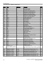
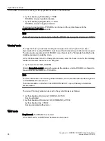
p99
ARRAY[0..20] of INT
13,18,23,0,0,0,0,0,0,
0,0,0,0,0,0,0,0,0,0,0
Program management (see
Distributed Positioning
Motor on PROFIBUS DP
user manual)
r/w
p100
INT
0
Control word simulation
r/w
p101
ARRAY[0..10] of INT
10(0)
Blocks 1 to 10 of the data structure for the POSMO
A parameters
r/w
p700
2)
INT
2
Operating mode
1 = speed-controlled mode
2 = positioning mode
r/w
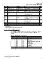
p701
2)
INT
0
Message frame substitution
r/w
p880
2)
REAL
4096
Normalizing of the speed at the gear output when
a setpoint of 4096 decimal is specified via the con‐
trol word (STW)
r/w
p930
INT
0
Current mode
1 = speed-controlled mode
2 = positioning mode
r
p964
ARRAY[0..7] of INT
8(0)
Drive identification
r
p1426
2)
REAL
100
Tolerance band for actual speed value
r/w
p1427
2)
INT
0
Delay time for "Ramp-up completed" signal
r/w
1)
r - read, w - write
2)
This parameter is new or extended with SIMOTION V4.1.
Structure of "Array_POSMOA_prgCtrlInfo"
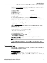
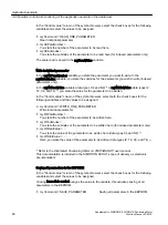
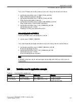
"Array_POSMOA_prgCtrlInfo" contains the program control word. Here, you can define the
behavior of a traversing block (see
Distributed Positioning Motor on PROFIBUS DP user
manual).
Table 3-6
Structure of Array_POSMOA_prgCtrlInfo
Array element
Data type
Initial value
Comment
0
BOOL
TRUE
Type of motion
1
BOOL
TRUE
Type of positioning
2
BOOL
FALSE
Type of timer
3
BOOL
FALSE
Connection between timer and start byte
4
BOOL
FALSE
Program return
5
BOOL
FALSE
Type of traversing
6
BOOL
FALSE
Invert start byte condition
7
BOOL
FALSE
SM start type
8
BOOL
FALSE
Program stop
9
BOOL
FALSE
Set actual value
Function blocks
3.5 Function block _POSMOA_rwAllParameter
Supplement to SIMODRIVE POSMO A Positioning Motor
Function Manual, 01/2015
37

