3.5 Status Model
57
3.5
Status Model
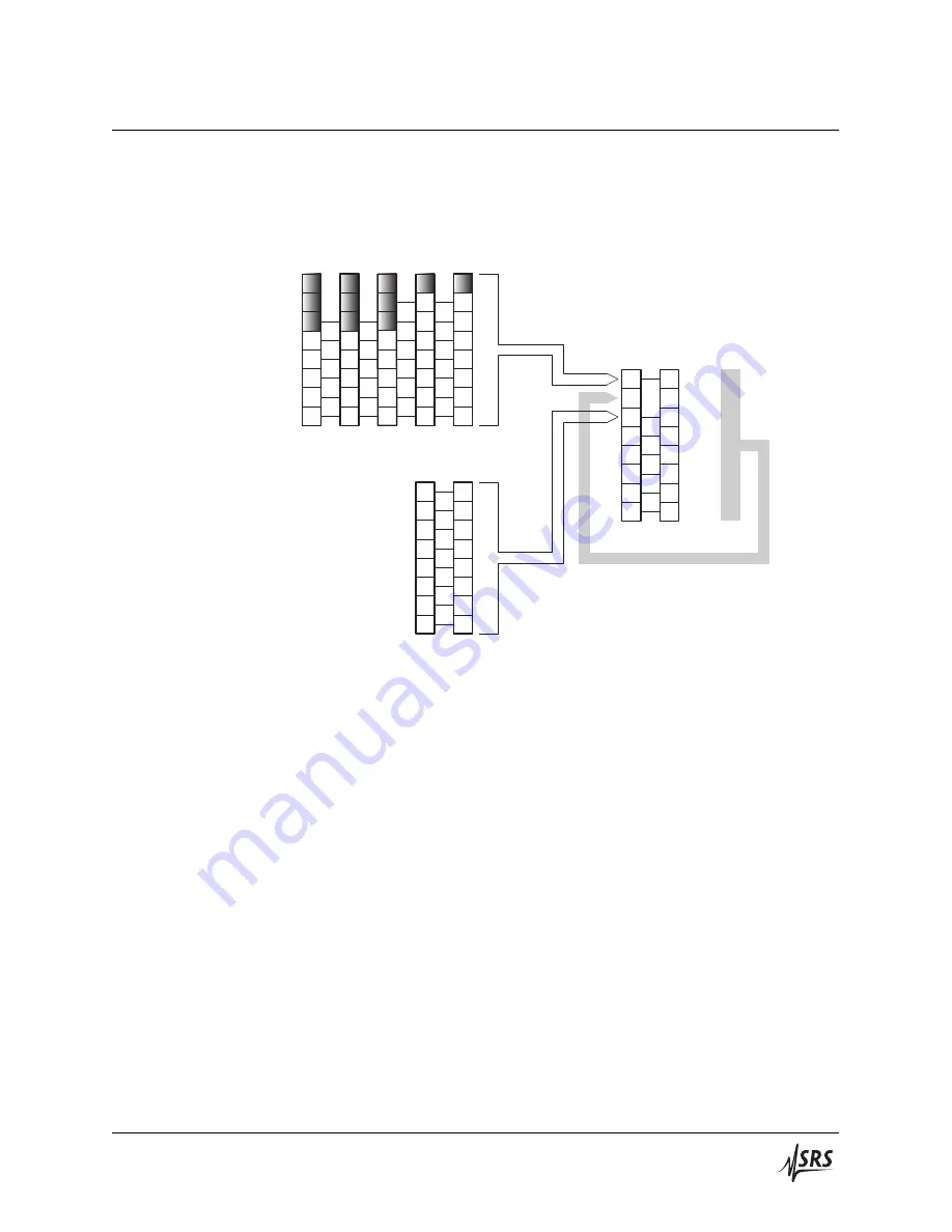
The SR542 status registers follow the hierarchical IEEE–488.2 format. A
block diagram of the status register array is given in Figure 3.1.
7
X
5
4
3
2
1
0
CHSB: Chopper Status Bit
MSS: Master Summary Status
ESB: Event Status Bit
undef
undef
7
6
5
4
3
2
1
0
Status Byte
SB
SRE
undef
undef
undef
OPC: Operation Complete
INP: Input Buffer Overrun
DDE: Device Error
EXE: Execution Error
CME: Command Error
URQ: User Request
PON: Power On
QYE: Query Error
ESR
ESE
Standard Event Status
6
5
4
3
2
0
6
5
4
3
2
0
1
1
7
7
CHCR CHPT CHNT CHEV CHEN
Chopper Status
EL: Ext Sync Lock
PL: Chopper Phase Lock
CMAX: Motor Current Max
MEMFAIL: Chop Head Memory Fail
MON: Motor On 0
1
0
1
0
1
0
1
0
1
4
3
2
4
3
2
2
2
2
3
3
3
4
4
4
5
5
FL: Chopper Frequency Lock
DISCONN: Chop Head Memory Fail
6
6
Figure 3.1:
Status Model for the SR542 Precision Optical Chopper.
There are five categories of registers in the status model of the SR542:
Condition Registers
: These read‑only registers correspond to the real‑time condition of
some underlying physical property being monitored. Queries re‑
turn the latest value of the property, and have no further side ef‑
fects. Condition register names end with
CR
.
Transition Selection Registers
: These read/write registers define specific transition events (posi‑
tive:
0 → 1
, or negative:
1 → 0
). The event is then defined by the
selected transition in the value of the underlying condition regis‑
ter. Transition register names end with
PT
or
NT
for positive and
negative transitions, respectively.
Event Registers
: These read‑only registers record the occurrence of defined events
within the SR542. If the event occurs, the corresponding bit is set
to 1. Upon querying an event register, any set bits within it are
cleared. These are sometimes known as “sticky bits,” since once
set, a bit can only be cleared by reading its value, or by issuing
the global
*CLS
Clear Status command. Event register names end
with
SR
or
EV
.
SR542 Precision Optical Chopper


