background image


Installation & Operation Manual for the 


13 

Active Vibration Cancellation (AVC) System 

13)


Display User lock state 
a)


Command: 

LOGIN<CR>


b)


Returns the User lock state. 

User lock states: 

0 – Controller parameters and features mark “User locked” are fully accessible. 
1 – Controller parameters and features mark “User locked” are restricted and write protected. 


14)


Clear User lock state 
a)


Command: 

LOGIN=<PASSWORD><CR>


b)


Enable access to the commands designated as “User locked.” 

c)


A return of 0 confirms that controller parameters are unlocked. 

d)


<PASSWORD>

 is the current user defined password. The default password is 

STIRLING


15)


Set User lock state 
a)


Command: 

LOGOUT=<PASSWORD><CR>


b)


Disable access to the commands designated as “User locked.” 

c)


A return of 1 confirms that controller parameters are locked. 

d)


<PASSWORD>

 is the current user defined password. The default password is 

STIRLING


16)


Display the current operating cryocooler type 
a)


Command: 

MODE<CR>


b)


Returns the current operating cryocooler type. 

Cryocooler Types: 

CT – The controller is configured to control CryoTel CT cryocoolers. 
GT – The controller is configured to control CryoTel GT cryocoolers. 
MT – The controller is configured to control CryoTel MT cryocoolers. 


17)


Display the cryocooler power as measured by the controller 
a)


Command: 

P<CR>


b)


Returns the cooler power in watts as measured by the controller. 


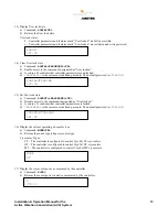
LOGIN 
001.00 


LOGIN=STIRLING 
000.00 


LOGOUT=STIRLING 
001.00 


MODE 
GT 


070.00 


Summary of Contents for AMETEK AVC

Page 1: ...Installation Operation Manual for the Active Vibration Cancellation AVC System Rev December 15 2014...

Page 2: ...Section 1 Equipment Description 3 System Components 3 Specifications 3 Section 2 Installation 4 Install the AVC Balancer 4 Install the Accelerometer 5 Attach the Wiring Harnesses 6 AVC Controller Over...

Page 3: ...ncludes an AVC balancer AVC controller over temp thermistor cable accelerometer cable power wiring harness and instrumentation wiring harness as shown in figure 1 Figure 1 Active Vibration Cancellatio...

Page 4: ...er from the cryocooler Now install the AVC balancer as follows 1 Unscrew and remove the hex standoff from the balancer figure 2 2 Screw the hex standoff onto the cryocooler end plate 3 Place the balan...

Page 5: ...ate of the CryoTel cryocooler with the provided 5 40 bolt into the end plate of the cryocooler figure 5 If the cryocooler is an older model not equipped with a 5 40 threaded hole then use a small amou...

Page 6: ...y Leads A black lead and a red lead that connect to the DC power supply not included for the cooler AVC Controller Power Wiring Harness Connector A D sub connector with various pin sizes that connects...

Page 7: ...s to the instrumentation wiring harness connector on the AVC controller Over Temp Thermistor Connector A small black two pin plastic connector that connects to the plastic connector on the over temp t...

Page 8: ...among the features of the standard CryoTel controllers is the reject over temperature alarm A provided thermistor figure 9 is attached to the cooling fins via the available threaded hole or near the w...

Page 9: ...Installation Operation Manual for the 9 Active Vibration Cancellation AVC System Figure 9 Over Temp Thermistor Cable Figure 10 Thermistor Attached to the Cryocooler with Epoxy...

Page 10: ...ol status of the controller a Command COOLER CR b This command displays the current control status of the controller Control Modes OFF The cryocooler is OFF or being powered down and turned OFF ON The...

Page 11: ...ag is active The LCD will flicker ON and OFF at approximately 0 4s interval The LCD s content will toggle between the regular data and an error screen The error screen will have the ERROR command s ou...

Page 12: ...l constant of the temperature control loop a Command KP CR b Returns the proportional constant of the temperature control loop 10 Set the proportional constant of the temperature control loop a Comman...

Page 13: ...Set User lock state a Command LOGOUT PASSWORD CR b Disable access to the commands designated as User locked c A return of 1 confirms that controller parameters are locked d PASSWORD is the current use...

Page 14: ...cked c Set commanded power when in power control mode as set by the COOLER POWER command d VAL is the target power in watts While any number from 0 0 to 999 99 can be input the controller will only co...

Page 15: ...s 25 Display target temperature in kelvin a Command TTARGET CR b Returns the target temperature of the controller in kelvin when in temperature control mode default mode 26 Set target temperature a Co...

Reviews: