C5535 DSPShield H/W Reference Manual
Version 0.1
In Collaboration with Stanford University
page
11
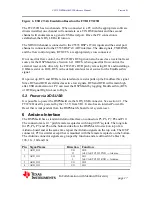
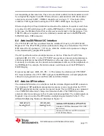
devices on the I2C bus on the DSPShield are listed in Table 7 along with their 7-bit
address.
I2C Peripheral
I2C Address
GPIO Expander 1
0x20
GPIO Expander 2
0x21
OLED Display
0x3C
AIC3204 Codec
0x18
DSP Expansion Connector
I2C Extension, +3.3V Logic Levels
Arduino Digital Interface
I2C Extension, Buffered at +5V Logic Levels
DSP_I2C_EN must be a logic ”1”
Table 7. Devices on the I2C Bus
The I2C bus is also extended to the Arduino and DSP Expansion Connectors. For the
DSP Expansion Connector, the bus remains at +3.3V levels and is not buffered. For the
Arduino connector, the I2C bus is buffered by a TI PCA9515B I2C Repeater IC. The IC
provides a translation between the Arduino’s +5V logic levels and the C5535 DSP’s
+3.3V logic levels. On power up and reset, the PCA9515B is disabled. This isolates the
DSPShield’s internal I2C bus during the boot sequence. After boot, the C5535 DSP can
enable the PCA9515B by setting DSP_I2C_EN on Port0.2 of GPIO Expander 2 to a “1”.
4 DSPShield Peripherals
In addition to the C5535 DSP’s internal peripherals, the DSPShield has several external
peripherals that increase its functionality. The peripherals are:
1.
Two TCA6416A 16-bit I2C to GPIO Expander chips
2.
OLED display
3.
TLV320ACI3204 Stereo Audio Codec
4.
Micro SD Card connector
5.
DIP Switch Inputs, LEDs, and Push Button Reset
6.
Additional peripherals can be added through the use of the 40-pin DSP Expansion
Connector and the Arduino Interface Connectors.
4.1 I2C GPIO Expander
The two TCA6416A (I2C to GPIO) Expander chips increase the number of GPIOs under
the C5535 DSP’s direct control. Each chip provides an additional 16 GPIOs. Tables 8a
and 8b list the direction (after programming) and function of each GPIO.
On power up and reset, all the GPIOs are initialized as inputs. Some GPIO pins have
external pull up or pull down resistors connected to them that allow the various
DSPShield external peripherals to power up in a known state. For example, the U3 4-bit
1to2 multiplexer’s select pin is connected to Expander 2’s Port0.4 GPIO and also to a


