C5535 DSPShield H/W Reference Manual
Version 0.1
In Collaboration with Stanford University
page
30
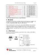
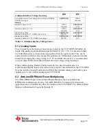
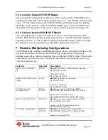
G2
R150=DNI, R165=0 Ohm, G2=Not Installed
FTDI FT2232H Clock Source is G2.
R150=0 Ohm, R165=DNI, G2=Installed
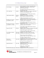
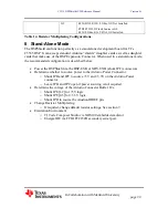
Table 14. Resistor Multiplexing Configurations
8 Stand-Alone Mode
The DSPShield can function perfectly as a stand-alone development board for TI’s
C5535 DSP. It can accept standard Arduino “shields” daughter cards as well as daughter
cards that make use of the DSP Expansion Connector. When used in a stand-alone mode,
the recommended configuration is described below:
x
Power the DSPShield via the DSP-USB or XDS-UXB (shunt JPF) connectors.
x
Determine whether to source power to the Arduino Power Connector.
o
Shunt JPB and JPC to 5V and +3.3V on the Arduino Power
connector.
o
Leave JPB and JPC open if power sourcing is not required.
x
Determine the voltage of the Arduino Connector Buffer ICs.
o
Shunt JPE[1-2] for +5V logic.
o
Shunt JPE[2-3] for +3.3V logic.
o
Shunt JPD to source the Arudion IOREF pin.
x
Change Resistor Multiplexing
o
If required, change default resistor settings. See section 7.
x
Emulation Environment
o
TI Code Composer Studio via XDS100 embedded emulator.
o
Energia IDE via FTDI FT2232H secondary serial port.

