C5535 DSPShield H/W Reference Manual
Version 0.1
In Collaboration with Stanford University
page
17
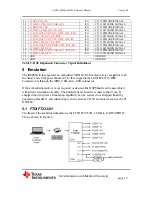
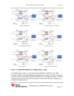
Figure 6. USB JTAG Emulation Based on the FTDI FT223H
The FT2232H has two channels. When connected to a PC with the appropriate software
drivers installed, one channel will enumerate as a TI XDS Emulator and the second
channel will enumerate as a generic USB serial port. Once the PC connection is
established, the XDS_LED will turn on.
The XDS100 channel is connected to the C5535 DSP’s JTAG inputs and the serial port
channel is connected to the C5535 DSP’s UART interface. The data signals, TXD/RXD,
and the flow control signals, RTS/CTS, are appropriately cross connected.
If not used for flow control, the FT2232H’s RTS pin can also be used as an external reset
source for the DSPShield (see Section 6.2). If RTS is being used for flow control, the
external reset can be driven by the FT223H’s DTR pin by removing R161 and installing a
0 Ohm resistor on R163. RTS is the default emulator reset source for the EmuResetSrc
signal.
On power up, RTS and DTR are tri-stated and a resistor pulls up the EmuResetSrc signal.
Since RTS and DTR are defined as active low signals, RTS and DTR will remain high
after USB enumeration. A PC can reset the DSPShield by toggling EmuResetSrc, (RTS
or DTR) signal High to Low to High.
5.2 Power via XDS-USB
It is possible to power the DSPShield via the XDS_USB connector. See section 2.1. The
FT2232H itself is powered by the +3.3V from VR1. It also has an internal Power-On
Reset that is independent from the DSPShield’s board level system reset.
6 Arduino Interface
The DSPShield has a standard Arduino Interface on connectors P5, P6, P7, P8 and P10.
The connectors are 0.1” pitch female receptacles with long 0.025”sq tails. The long tails
for P5, P6, P7, and P8 on the bottom side allow the DSPShield to stack on top of an
Arduino board and at the same time repeat the Arduino signals on the top side. The ICSP
connector, P10 is similar except that is mounted with the female receptacle on the bottom.
The Arduino connector signals are grouped by function and are defined in Tables 10a,
10b, 11c, 10d and 10e.
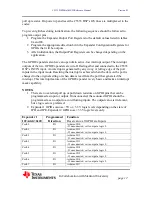
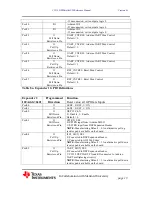
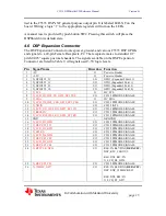
Pin Signal Name
Direction Function
1
ARD_IO0
I/O
O
I/O0
Alt: UART C5535 TXD
ĺ
Arduino
2
ARD_IO1
I/O
I
I/O1
Alt: UART C5535 RXD
ĸ
Arduino
3
ARD_IO2
I/O
I/O2
4
ARD_IO3
I/O
I/O3


