C5535 DSPShield H/W Reference Manual
Version 0.1
In Collaboration with Stanford University
page
23
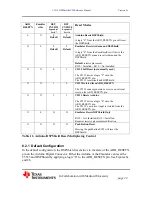
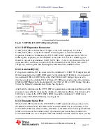
6.2.2 C5535 Isolated from ARD_RESETN pin
In this configuration, the DSPShield is disconnected from the ARD_RESETN pin. Only
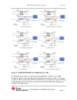
the Emulator EmuResetSrc or the push button can reset the DSPShield. See Figure 8c
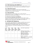
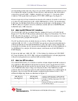
6.2.3 C5535 Resets Arduino
In this configuration, the DSPShield’s own reset input is isolated from the
ARD_RESETN pin. At the same time it drives a logic “0” onto the ARD_RESETN pin
and therefore resets the Arduino. See Figure 8d.
6.2.4 C5535 Self Resets
In this configuration, the C5535 generates a logic “0” that is routed to the
ARD_RESETN pin and also to the DSPShield’s reset circuitry. This is a “circular” reset
that will cause the C5535 to reboot. See Figure 8e.
6.2.5 Emulator Only Resets the DSPShield
There may be some application that requires that the emulator be able to reset the
DSPshield without resetting the Arduino. In this case, by switching R119 and R122, the
EmuResetSrc signal is isolated from the ARD_RESETN pin. See Figure 8f.
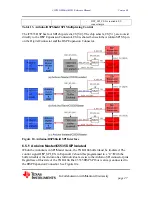
6.3 DSPShield UART Multiplexing
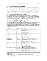
The C5535 DSP’s UART peripheral can be connected to the DSP Expansion Connector,
Arduino Digital Header IO0 and IO1 pins, or the XDS100 JTAG Serial Port. The
multiplexing of the UART signals are controlled by UART_MUX_SEL and
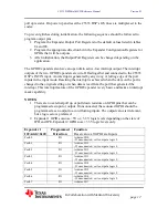
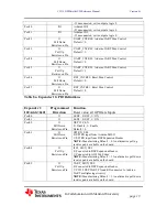
UART_CNTRL[3:0] via the GPIO Expanders. Table 13 lists the 4 multiplexing modes
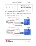
used in most applications. The different UART Multiplexing Modes are illustrated in
Figure 9.
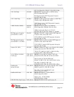
UART_
MUX_
SEL
Expander2
Port0.5
ARD_
UART_
CNTRL3
Expander1
Port1.5
ARD_
UART_
CNTRL2
Expander1
Port1.4
ARD_
UART_
CNTRL1
Expander1
Port1.3
ARD_
UART_
CNTRL0
Expander1
Port1.2
C5535 UART Connection Modes
0
1
0
1
0
DSP Expansion Connector Mode
C5535 UART
ļ
DSP Expansion Header
ARD_IO[1:0]: No connection
XDS SerPort: No connection
1
1
0
1
0
Default Communications Mode
C5535 UART
ļ
ARD_IO[1:0]
ARD_IO1: No connection
A XDS SerPort TxD
ĺ
C5535 RxD
XDS SerPort RxD
ĸ
C5535 TxD
1
0
0
0
0
Arduino Communication Mode


