background image

Setting

Variable

Line

Feed

Spacing

ESC

TninO

 (1B)(54)n1n0

Hex

(27)(84)n1n0

Decimal

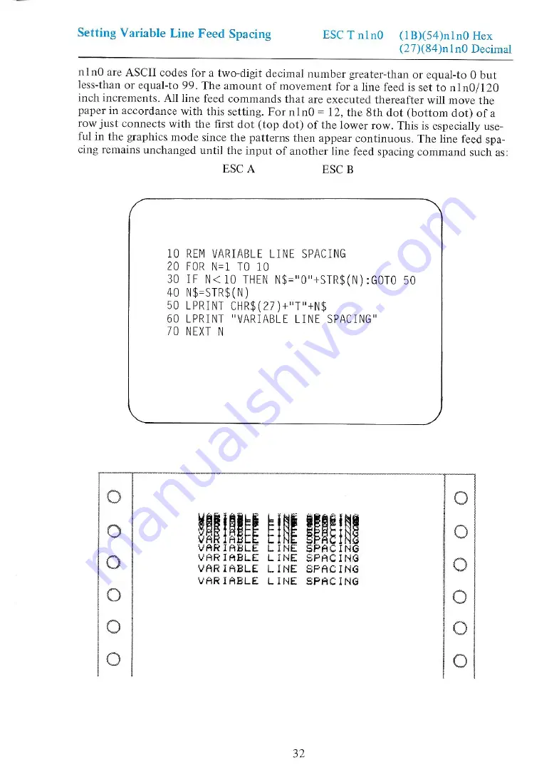
nlnO

are

ASCII

codes

for

a

two-digit

decimal

number

greater-than

or

equal-to

0 but

less-than

or

equal-to

99.

The

amount

of

movement

for

a

line

feed

is

set

to

n1n0/120

inch

increments.

All

line

feed

commands

that

are

executed

thereafter

will

move

the

paper

in accordance

with

this

setting.

For

nln0

=

12,

the

8th

dot

(bottom

dot)

ofa

row

just

connects

with

the

first

dot

(top

dot)

of the

lower

row.

This

is

especially

use-

ful

in

the

graphics

mode

since

the

patterns

then

appear

continuous.

The

line

feed

spa-

cing

remains

unchanged

until

the

input

of

another

line

feed

spacing

command

such

as:

ESC

A

ESC

B

(

>)

10

REM VARIABLE

LINE

SPACING

20

FOR

N=1

TO

10

30

IF

N<10

THEN

N$="0"+STR$(N):GOTO

50

40

N$=STR$(N)

90

LPRINT

CHR$(27)+"T"4N$

60

LPRINT

"VARIABLE

LINE

SPACING"

70

NEXT

N

PEE

Be

VARIABLE

LINE

SPACING

VARIABLE

LINE

SPACING

VARIABLE

LINE

SPACING

VARTABLE

LINE

SPACING

OoO000

0

O0O000

0

Summary of Contents for Transtar 315

Page 1: ...Tran Star 315 Color Graphics Printer Operator s Manual ...

Page 2: ...cord into a 110V AC outlet 6 With the power turned OFF depress and hold the Line Feed switch down and turn the power ON The printer will automatically perform a self test to check its operation When the printer stops printing turn the power OFF 7 Connect the Transtar 315 to your computer with the cable 8 Transmit characters to your printer by running one of the sample programs in Section 4 9 Refer...

Page 3: ...Transtar 315 Color Graphics Printer Operators Manual ...

Page 4: ...pyright 1983 Vivitar Computer Products 2100 116th Avenue N E P O Box C 96975 Bellevue Washington 98009 phone 206 454 9250 Printed in the United States of America Transtar and Seikosha reserve the right to change the contents as stated herein at any time and without notice Although every effort has been made to insure that the contents as sta ted herein are complete and without error Transtar and S...

Page 5: ...ition Adjustment Self test Printing Automatic Printing Function Error Conditions Caring for your Printer 3 Configuring your Printer Making a Cable Electrical Condition Timing Chart Setting the Dip Switches 4 Programming your Printer Appendix A Using the Optional PICS Interface Appendix B ASCII Code Table Appendix C Troubleshooting Guide Appendix D Color Tips Appendix E Using the PICS Card Under CP...

Page 6: ... you how to use the printer in everyday applications Part 3 provides the information you need to do the initial set up of the printer Part 4 provides technical details for those persons interested in programming the Transtar 315 Appendices a glossary of selected terms and an index will provide further assistance as you learn to use the Transtar 315 ...

Page 7: ...nology provides 7 color mixing in a single pass of the printhead The Transtar 315 uses a Centronics compatible parallel interface An optional Apple II Tle and Franklin PICS interface allows for softwarc independent graphics printing Thus most business and entertainment programs can be printed by simply depressing the printer s COPY button The optional Serial Interface Board allows for interfacing ...

Page 8: ...t level 5 x 8 horiz x vert 1 dot space 7 x 8 horiz x vert 1 dot space Alphanumeric English character set and symbols 8 x 9 horiz x vert 10 0 cpi 6 x 9 horiz x vert 13 3 cpi 10 cpi and 13 3 cpi 80 cpl and 106 cpl 38 cps and 50 cps 1 6 1 8 and N 120 inch software selectable Original 2 copies 15 Ib paper color is only on the original Arbitrary combinations of any color of dot in in an 8 dot column wi...

Page 9: ...Parts of the Printer i _ Upper case A Paper feed Figure Printer cover ...

Page 10: ...pushed b If held down line feeds are continuously executed c Line feeds are performed only in the STOP condition 4 FORM FEED switch a Pressing this switch causes a form feed to the top of the next page or next Top of Form b This switch is valid only in the STOP condition 5 COPY switch a Pressing this switch causes a screen copy to occur b After a single screen copy is complete the copying conditio...

Page 11: ...stance 7 lines in 1 6 inch line feed mode printing won t be executed unless paper is inser ted to clear the PAPER EMPTY condition COPY lamp green a This lamp blinks when a screen copy starts b It stops blinking when a screen copy terminates c The lamp blinks when the STOP switch is pressed during a screen copy Pressing the STOP switch again causes the lamp to stay on and the screen copy to continu...

Page 12: ..._ Part 2 Installation Use ...

Page 13: ...ngle figure 5 and put into posi tion from the right side The A portion of the ribbon must slide between the printhead and the metal slit e Push on the lower right side of the cassette with the index finger as shown in figure 5 The cas sette should click into place If you don t hear a click turn the cassette knob a little more in the direction of the arrow and press again on the right side of the c...

Page 14: ... pushing the respec tive cartridge lever figure 7 to ward the outside of the cassette Pushing in the cartridge lever starts the transfer of ink again It is important to turn off the ink transfer from unused colors Fail ure to do so will cause over inking of the ribbon leading to streaking 2 Removal a The ink cassette is easily removed by grasping the cassette as shown in figure 8 with the thumb on...

Page 15: ...single ink cartridge can be replaced when that particular color is used up Remove the car tridge by gently pinching inward on the metal clip D as shown in figure 10 b Then push outward on the car tridge lever as shown in figure 11 Insert the new ink cartridge Be sure that the color of the new ink cartridge matches the color indicator Jabel on the top of the cassette Pinch the metal clip gently and...

Page 16: ... head adjustment lever all the way toward the front of the printer refer to the section on the Head Position Adjustment c Use both hands to insert the paper from the rear and turn the right paper feed knob in a clockwise direction figure 14 This causes the paper to feed around the printhead and the platen Note that the paper feed knob can be rotated in either the clockwise or counter clockwise dir...

Page 17: ...ng the fric tion rollers on the bar so that they rest directly on top of the two large rubber tractor rings figures 15 and 16 If the tractor spacing does not match the paper width slide the tractors to the left or right as needed Make sure that the paper is positioned so that the first and last print positions are on the paper f Return the head adjustment lever to its original position Replace the...

Page 18: ...of the operations are the same Note 1 For proper friction feed be sure that the friction rollers are positioned directly on top of the rubber tractor rings and that these two sets of rol lers properly grasp the paper figure 19 2 The paper empty switch is Figure 19 located about 2 inside the left side of the printer case on the metal base plate The left edge of the single sheet paper must cover the...

Page 19: ...f the click holes The head is adjusted by moving the lever toward 8 for thick paper or multiple copies and toward for single sheets of lightweight paper The printer is shipped with the lever foot set to position 3 the ideal position for a single sheet The lever foot should be set to 8 for insertion and removal of the ribbon Red mark Head adjustment lever Lever foot Click holes DOO Figure 20 ...

Page 20: ...line the text starts printing even though a print command was not received The portion of the text that exceeds the line length is printed on the next line If however graphics data including repeated graphics printing is input that exceeds the line length that portion of the data exceeding the line is ignored The mode is not changed in either case Error Conditions When the printer enters an error ...

Page 21: ... properly in stalled Failure to do so may cause damage to the printhead and or platen Be careful to insure that paper is being supplied properly to the printer Be particularly careful when using multiple part forms The paper should be placed as near to the printer as possible and at the same height as the printer With the printer on a table avoid supplying paper from a lower level like the floor S...

Page 22: ...or color graphics Apple I Ile or Franklin users can easily use all of the features of the Transtar 315 with the optional PICS interface This interface card allows the printing of color graphics by simply depressing the COPY button on the printer A software graphics driver routine is available through your local dealer for non PICS card use IBM Personal Computer users can print high and medium reso...

Page 23: ...ard Centronics parallel port Input in the Input Output column indicates an input signal into the printer Output refers to the output from the printer 4 PIN SIGNAL IN OUT PIN SIGNAL IN OUT 1 STROBE IN 19 GROUND 2 DATA 1 20 3 DATA 2 21 4 DATA 3 22 5 DATA 4 23 6 DATA 5 24 7 DATA 6 25 8 DATA7 26 9 DATA 8 27 10 ACK OUT 28 11 BUSY 29 12 PAPER EMPTY 30 13 NC 31 INITIAL IN 14 GROUND 32 ERROR OUT 15 NC 33 ...

Page 24: ...nal is always output at the very end of the BUSY signal It can be used to indicate that the printer is request ing more data Note The BUSY and ACK signals are always output every time the printer inputs data ERROR This signal goes LOW when the printer enters an error condition In this case the printer s control circuitry shuts down There are 2 ways to clear this condition 1 Turn the printer off fo...

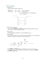
Page 25: ...output lines are pulled up to 5 0 V with a 1OK ohm resistor Input signals The input loading is equivalent to a single 74LS04 gate input Output signals The output is equivalent to the output of a single 74LS04 gate The recommended load for the outputs is a single TTL or LSTTL input gate 100Q linput 74 LS 04 equvalent 1000 PF L The STROBE and INITIAL signals are pulled up to 5 0 V with a 1000 ohm re...

Page 26: ...sted pairs with the GND lines or alternated with GND lines when flat cable is used STROBE INITIAL BUSY ACK ERROR Timing chart a During data input DATA1 8 i of es ean 1 us MIN STROBE ef MI 0 0 5 us fe r Os MIN _ t_ BUSY TR a ACK L___ _ 5 10 us TB character codes 50 ps or longer varies with the data FF CR LF codes printing line feed and carriage return 21 ...

Page 27: ...l care should be taken in gently removing the upper case as it and the circuit board are connected with a cable Factory No Function ON OFF Setting I Selection of Print black on Print black on black and white screen as black screen as white OFF on screen on printer on printer 2 Self test printing Activate printing No printing OFF 3 CR code meaning Carriage return Carriage return OFF and line feed o...

Page 28: ...xamples in MBASIC of how to program the printer for each of these functions Each code is described followed by the Mbasic listing as you should type it and the resulting output as it will be printed on the paper These examples will help you become acquainted with the printer s features and how to access them The outline of the video screen displays what you should type on your keyboard The resulti...

Page 29: ... in each example 1 Add line 1 to read PR 1 2 Add line 1000 to read PR 0 3 Change all lines that read LPRINT to PRINT Example 10 REM REPEATED GRAPHICS PRINTING 20 REM PRINT DECIMAL 75 70 TIMES 30 LPRINT LPRINT LPRINT 40 LPRINT CHR 28 CHR 70 CHR 75 Before PR L 10 REM REPEATED GRAPHICS PRINTING 20 REM PRINT DECIMAL 75 70 TIMES 30 PRINT PRINT PRINT 40 PRINT CHR 28 CHR 70 CHR 75 1000 PR 0 After 24 ...

Page 30: ... feed spacing to 6 lines per inch ESC B Set line feed spacing to 8 lines per inch POS n2 nl nO Specifies print position by character location This three ESC POS nH NL ESC Zn ESC Z 00 H n ESC N ESC G digit decimal number is equal to or greater than 0 but less than or equal to 105 Specifies print position in dot units This two byte hexade cimal number must be equal to or greater than 0 but less than...

Page 31: ...Specifies color selection This may be used in both graphics and text mode ESC C Specifies color for individual dots in the horizontal RGB n2nln0Om2m1m0 _ raster scan graphics mode ESC P Specifies color for individual dots in the horizontal head n2nInOm2m1lm0 hammer raster scan graphics mode ESC D Specifies single pass of graphics printing ESC E Specifies 2 pass color graphics printing Effective fo...

Page 32: ... means that no line feed is executed Refer to Part 3 on Dip Switch Settings for instructions on changing switches If there is no data in the buffer or if all of the data are spaces the printhead does not move 10 REM CARRIAGE RETURN EXAMPLE 20 LPRINT LPRINT LPRINT 30 LPRINT THIS IS A SAMPLE LINE 40 LPRINT CHR 13 50 LPRINT WITHOUT LINE 40 THIS WOULD BE ON THE SAME LINE AS ABOVE THIS IS A SAMPLE LINE...

Page 33: ...ffer or if all of the data are spaces a line feed alone is executed The line feed spacing is set by any of the following commands ESC T nl nO ESC A ESC B 10 REM LINE FEED EXAMPLE 20 LPRINT LPRINT LPRINT 30 LPRINT HERE IS THE LINE FEED EXAMPLE 40 LPRINT CHR 10 REM LINE FEED COMMAND 50 LPRINT TEXT AFTER A LINE FEED HERE IS THE LINE FEED EXAMPLE TEXT AFTER A LINE FEED O O O000 0 28 ...

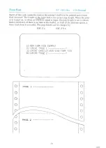
Page 34: ...set page length When the pow er is turned on or when an INITIAL signal is input the page length is set to eleven inches 66 lines If there is no data in the buffer or if all of the data are spaces a form feed alone is executed The page length can be changed by ESC Zn ESC Z0n 10 REM FORM FEED EXAMPLE 20 LPRINT PAGE 1 30 LPRINT CHR 12 REM SEND FORM FEED 40 LPRINT PAGE 2 ...

Page 35: ...to clear double width printing and return to standard width print When the power is turned on or when an INITIAL signal is sent from the computer the printer is set to the standard width print format SI 7 10 20 30 40 50 60 70 REM DOUBLE WIDTH PRINT EXAMPLE LPRINT LPRINT LPRINT LPRINT LPRINT LPRINT LPRINT LPRINT NORMAL WIDTH CHRS 14 3 REM TURN ON DOUBLE WIDTH PRINT DOUBLE WIDTH CHR 15 3 REM TURN OF...

Page 36: ... the CAN code is cleared However the printer mode is not cleared 10 REM CLEAR BUFFER EXAMPLE 20 LPRINT THIS IS BEING INPUT TO THE BUFFER 30 LPRINT CHR 24 REM SEND CAN CODE 40 LPRINT THIS IS PRINTED AFTER THE CLEAR BUFFER CODE O tie 18 eae aren Tae crear sure cove 0 O 0 O 0 O 0 O O O 0 O O O 31 ...

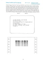
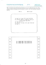
Page 37: ...For nln0 12 the 8th dot bottom dot ofa row just connects with the first dot top dot of the lower row This is especially use ful in the graphics mode since the patterns then appear continuous The line feed spa cing remains unchanged until the input of another line feed spacing command such as ESC A ESC B 10 REM VARIABLE LINE SPACING 20 FOR N 1 TO 10 30 IF N 10 THEN N 0 STR N GOTO 50 40 N STR N 90 L...

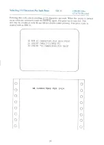
Page 38: ...the line feed spacing is auto matically set to 1 6 inch The setting remains unchanged until the input of another line feed spacing command such as ESC B ESC T nin0O 10 REM 1 6 LINES PER INCH SPACING 20 LPRINT CHRS 27 CHR 65 REMSET 1 6TH LINES PER INCH 30 FOR K 1 TO 3 40 LPRINT 6 LINES PER INCH SPACING 50 NEXT K 6 LINES PER INCH SPACING 6 LINES PER INCH SPACING O OO00 0 0 0 6 LINES PER INCH SPACING...

Page 39: ... setting remains unchanged until the input of another line feed spacing command such as ESC A ESC T nlnO 10 REM 1 8 LINES PER INCH SPACING 20 LPRINT CHR 27 CHR 66 REM SET 1 8TH LINES PER INCH 30 FOR K 1 TO 3 40 LPRINT 8 LINES PER INCH SPACING 50 NEXT K NES PER INCH SPACING NES PER INCH seaciNe 8 LI1 LIb B LINES PER INCH ACING O0O 00 0 O 0 0 34 ...

Page 40: ...home or starting left column posi tion n2n1n0 000 The 80th character position is n2n1n0 079 This specification can be made in either text or graphics mode In double width printing mode n2n1n0 is still calculated to be the number of standard size character spaces 10 REM CHARACTER POSITION EXAMPLE 20 LPRINT 1 30 LPRINT CHR 16 020 REM MOVE TO THE 20TH POSITION 40 LPRINT 20 50 LPRINT CHR 16 040 REM MO...

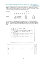
Page 41: ... 1 10 144 10 60 1st dot position 2 10 88 10 The specification of printing position can be performed as many times as desired However if a position is specified that already has data there the resultant output will be as though two characters or graphics patterns were printed one on top of the other cr 10 REM POSITION BY DOT COLUMN 20 LPRINT 1 30 LPRINT CHRS 27 CHRS 16 CHRS O CHRS 15 3 REM MOVE TO ...

Page 42: ... The spacing for one line is 1 6 inch Therefore n 6 will set the page length to 1 inch 1 6 x 6 1 inch The top of page one is redefined as the paper po sition when this code is input The page length counting begins there and is done by lines 10 REM PAGE LENGTH BY LINES 20 REM SET 12 LINES 30 LPRINT CHR 27 Z CHR 12 REM SET TO 12 LINES 40 LPRINT TOP OF PAGE ONE 50 LPRINT CHR 12 REM SEND FORM FEED 60 ...

Page 43: ...ater than 22 the result is as if 22 were set The top of page one is redefined as the paper position when this code is input The page length counting begins there and is done by inches On power on of the printer eleven inch paper is assumed 10 REM SET PAGE LENGTH IN INCHES 20 LPRINT CHR 27 Z CHR 00 CHRS 3 REM SET LENGTH TO 3 INCHES 30 LPRINT TOP OF PAGE ONE 40 LPRINT CHR 12 REM SEND FORM FEED 50 LP...

Page 44: ...ower is turned on or when the computer sends an INITIAL signal this print size is selected This size may be combined with SI and SO for double width printing This print mode is cleared with an ESC G r 10 REM 10 CHARACTERS PER INCH PRINT 20 LPRINT CHR 27 CHRS 78 30 LPRINT 10 CHARACTERS PER INCH 16 CHARACTERS PER INCH OQ oO 0 oO O000 0 00 0 39 ...

Page 45: ... more printing columns This mode can be used with SI and SO for double width printing Clearing of this mode is accomplished with an ESC N code or by turning the printer off 10 REM 13 3 CHARACTERS PER INCH 20 LPRINT CHR 27 CHR 71 30 LPRINT 13 3 CHARACTERS PER INCH 40 LPRINT CHR 27 CHR 78 REM BACK TO 10 CHARACTERS PER INCH 50 LPRINT NOW BACK TO 10 CPI 43 3 CHARACTERS PER INCH NOW BACK TO 18 CPI OOO ...

Page 46: ...is a three digit decimal number equal to or greater than 1 but less than or equal to 640 If n2n1n0 is 0 the command string ESC K n2n1n0 are ignored The correspondence between graphics data and the dots printed is that the uppermost dot dot 1 is represented by the lowermost bit D1 and the lowermost dot dot 8 is represented by the uppermost bit D8 Example e Ist dot 2 e 2nd dot 4 oO 3rd dot D8 D7 D6 ...

Page 47: ...Dot Graphics Example 7 10 REM EXAMPLE GRAPHICS 20 LPRINT CHR 27 KOO1 CHR 75 30 LPRINT OO2 00 0 42 O LO LO ...

Page 48: ... data n specifies the number of times the graphics data is to be printed when nis equal to or greater than O but less than or equal to 255 Using the same graphics data you created in the Dot Graphics section the example below will illustrate how to print the graphics data 70 times 10 REM REPEATED GRAPHICS PRINTING 20 LPRINT CHR 28 CHR 70 CHRS 5 43 ...

Page 49: ...HR 1 REM MAGENTA 50 LPRINT HERE 1S MAGENTA 60 LPRINT CHR 20 CHR 2 REM RED 70 LPRINT HOW ABOUT RED 80 LPRINT CHR 20 CHR 3 REM PURPLE 90 LPRINT PURPLE 100 LPRINT CHR 20 CHR 4 REM GREEN 110 LPRINT MY LAWN IS GREEN 120 LPRINT CHR 20 CHR 5 REM CYAN 130 LPRINT THE SKY IS BLUE 140 LPRINT CHR 20 CHR 6 REM YELLOW LPRINT THE BANANA IS YELLOW Black Magenta pink Red Purple Green Cyan light blue Yellow aIl 5B ...

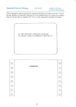
Page 50: ...e repeated printing of a single character n speci fies the number of times the character is to be printed where n is equal to or greater than 0 but less than or equal to 255 If n 0 the character is printed 256 times 10 REM REPEATED CHARACTER PRINTING 20 LPRINT CHR 27 CHR 82 CHR 8 A RAARA AAA 0000 00 45 ...

Page 51: ...e raster scan RGB mode followed by n2n1n0 and m2m1m0 which specify the number of dots to be printed in the horizontal direction and the number of dots to be printed in the vertical direction This is then followed by N x M bytes of data N n2n1n0 and M m2m1 m0 Both N and M must be within a range of 001 and 640 Each dot is represented by one byte which specifies the color for that dot as follows D8 D...

Page 52: ...e of yellow and cyan O l il yellow _ oe 1 0 0 purple a Mixture of cyan and magenta 1 0 1 magenta reddish purple 1i1fo lig 1f fi Note White means that the printer prints nothing OO VU 50 FOR J 1 TO 800 LPRINT CHR 1 3 NEXT J 60 NEXT I oS red Be ren ae yellow purple cyan 47 10 REM RASTER SCAN RGB EXAMPLE 20 FOR I 0 TO 6 30 LPRINT 40 LPRINT CHR 27 C050016 3 REM 050 HORIZONTAL DOTS 016 VERTICAL DOTS ...

Page 53: ...e number of rows of data that will be input This is then followed by the exact number of data specified in n2n1n0 and m2m1m0 Each dot is represented by one byte with the color being selected as shown below D8 D7 Do DS D4 D3 D2 D1 x X Xx xX p4 P3 P2 Pl P4 P3 P2 Pl corresponds to the colors produced by the individual hammers Pl yellow P2 magenta P3 cyan P4 black There are eight combinations of of Pl...

Page 54: ...le 10 REM PRINT HAMMER EXAMPLE 20 FOR I 0 TO 6 30 LPRINT 40 LPRINT CHR 27 P050016 REM 050 HORIZONTAL DOTS 016 VERTICAL DOTS 50 FOR J 1 TO 800 60 LPRINT CHR I 70 NEXT J 80 NEXT I 90 LPRINT yellow magenta cyan green purple O O O O 0 O O 0 49 0 ...

Page 55: ...selected Most of your normal graphics should be printed in this mode This mode is cleared only by an ESC E control code 10 REM SINGLE PASS GRAPHICS PRINTING 20 LPRINT CHR 27 CHR 68 REM SELECT SINGLE PASS GRAPHICS NOTE No example is provided Use of the Apple Screen Output software or the optional Apple PICS interface will demonstrate its use more fully You may wish to try running this program then ...

Page 56: ...ery dot color fill This gives the ribbon time to re ink and also extends the life of the ribbon 10 REM DOUBLE PASS GRAPHICS MODE 20 LPRINT CHR 27 3CHR 69 REM SELECT DOUBLE PASS MODE NOTE No example is provided Use of the Apple Screen Output software or the optional Apple PICS interface will demonstrate its use more fully You may wish to try running this program then typing in the RGB raster scan g...

Page 57: ...ext convert the columns to binary digits Read columns thru 7 from the bottom up A B Column 1 0000 1000 2 0001 0100 3 0010 0010 4 1100 0001 0010 0010 6 0001 0100 7 0000 1000 Now using Appendix B the ASCII code table convert the binary numbers to their decimal equivalent Column A refers to the top column and Column B refers to the rows For column 1 find 0000 then look down the side rows to find 1000...

Page 58: ...ION 40 IF CL 7 THEN CL 0 REM INCREME NT COLOR 50 L PRINT CHRS 20 CHRS CL REM SET COLOR 60 L PRINT CHRS 27 KOO7 CHRS 8 CHRS 20 CHRS 34 CHRS 193 CHRS 34 CHRS 20 CHRS 8 70 CL CL 1 REM INCREMENT COLOR 80 NEXT K 90 END In line 60 CHR 27 K sets the graphics mode The 007 is the number of graphics data that will follow The CHR 8 CHR 20 are seven graphics data calculated earlier i 53 O 00 ...

Page 59: ... highlight a word You will want to print the lighter color highlight color first then the darker text characters 7 WO 10 20 30 40 50 60 70 80 L L L REM HIGHLIGHTING EXAMPLE PRINT CHRS 16 020 REM MO VE TO THE 20TH CHARACTER POSITION PRINT CHRS 20 CHRS 5 REM SELECT CYAN PRINT CHRS 28 CHRS 90 CHRS 255 REM PRINT 90 COLUMNS OF Y ELLOW PRINT CHRS 20 CHRS 0 REM SELECT BLACK PRINT CHRS 16 020 REM MO VE TO...

Page 60: ...turned OFF Fail ure to do so when installing the PICS card could result in damage to your com puter and to the interface card Gently open the top cover and insert the PICS card into slot 1 You may have to rock it into place Slot 1 on the Apple II or II Plus is the second slot from the left On the Apple Ile slot 1 is the first slot on the back left 2 Plugging in the Cable Looking at the PICS card m...

Page 61: ...fter depressing the COPY button the computer waits for a letter sequence If any other letter other than the ones listed below are depressed the printer starts printing All options are toggles on or off by depressing the appropriate letters The default selections are in bold face Letter Option Dot Pattern Dot per dot or Fill Horizontal Size Normal or Expanded Vertical Size Normal or Expanded Locati...

Page 62: ...COPY switch type the option letter sequence and press the RETURN or SPACE BAR key Compatibility The PICS Interface is compatible with software programs that do not use the 6502 microprocessor interrupts Apple Pascal is compatible with the PICS card However because CP M uses the Z80 microprocessor it is not compa tible BOTH Dip Switches Apple II II Plus 48K ON Apple II II Plus 64K OFF Apple Ie 64K ...

Page 63: ... wor fury 133 fia res 187 197 213 229 245 6 F v ro é ja fv v O110 el 22 Ba ro fae fier fis 134 150 ice 182 ios Pia 30 246 oll i 7 G Ww iow é a Ww w 7 LB Iss Jal_Je7 _ fios _ ii 3s fist fier fies fase ais 331 par CAN 8 1H x hoo e x x 1000rs Pal s6 J73 ise fos 120 136 152 tes 184 f200 216 232 248 9 1 Y i y gc f y_ly tool eo ps far 57 73 5 Dios 121 137 _f0s3 169 ies 201 217 233 249 LE hy Zz Ii ty Zit...

Page 64: ...heck to make sure that the cable connecting the printer and compu ter is correctly connected 2 The ribbon cassette is not properly installed Properly install the ribbon cassette The printer is operating properly but the paper is not feeding through properly 1 The paper is jammed in the printer Remove the paper and reinsert it properly The print is light or smeared 1 The printhead position is not c...

Page 65: ...the old ink cartridge with a new ink cartridge 5 The ribbon has been used too long Replace the old ribbon cassette with a new one The POWER lamp is blinking 60 1 An ERROR condition has occurred due to the detection of abnormal timing in a sensor Turn power off and then back on again or input the INITIAL signal ...

Page 66: ...o prevent staining of the lighter colored bands on the ribbon Continuous printing of lighter colors on top of darker colors will contaminate the lighter band on the ribbon If this occurs continuous printing and re inking in the proper sequence of light color then dark color print will improve the color on the stained ribbon In normal operation the sequence of printing dark colors then light colors...

Page 67: ...he Z 80 card manual 2 Put this working disk in drive A and boot it up 3 Enter DDT by typing DDT RETURN 4 Enter the data needed to patch the CP M I O section by typing 100 RETURN 5 DDT will prompt with 0100 01 which means it is ready to accept the value to be placed at memory location 100 Enter all of the values in Table 1 by typing each value followed by a RETURN ADDRESS DATA 0100 01 00 F270 oo O0...

Page 68: ...corrections 9 When everything is correct exit from DDT by typing GO RETURN 10 Save the file that you have just created by typing SAVE 1 PATCH COM RETURN 11 Run the program to reconfigure your I O by typing MBASIC CONFIGIO RETURN 12 The computer will prompt Can your Apple Display Lower Case Y N 13 Type in Y if you have a lower case adapter N if you do not 14 The program will then ask you to choose ...

Page 69: ...rompt Destination drive A F Type A The modified I O routines are now a part of the CP M system on this disk Because CP M treats Control J as a TAB function this patch changes the control character to Control Y instead of the usual Control I 64 ...

Page 70: ...nty period subject to the con ditions stated below Exclusions The Limited Warranty provided by Transtar does not cover 1 Damage due to shipping or handling of the product 2 Damage due to misuse or abuse of the product either mechanical or electrical 3 Misoperation due to unauthorized repair or modification 4 Supplies ribbons or preventative maintenance 5 Consequential damages of any sort This Limi...

Page 71: ...equence a software code ESC followed by a sequence that is sent to the printer to alter the special print functions Form feed the movement of paper up a set amount of lines usually to the next page or Top of Form Friction feed a mechanism for moving paper around the platen by pressing it between two rubber rollers Similar to the function of a typewriter LPI lines per inch The number of printable l...

Page 72: ... 22 27 Dip Switch Settings 22 27 Dot Graphics 41 43 Double Pass Graphics Printing 51 Double Width Printing 30 Electrical Conditions 20 Error 21 Error Conditions 15 ESCA 25 67 ESCB 25 ESCD 26 ESCE 26 ESCG 25 ESC K 26 ESC K n2nin0 26 ESCN 25 ESC P n2n1n0 m2m1m0 26 ESC POS nHnL 25 ESCRCD 26 ESC TninO 25 ESC Z 00 Hn 25 ESC Zn 25 External Dimensions 3 FCC Notice ii FF 29 Form Feed 29 Form Feed Switch 5...

Page 73: ...y Dot Column 36 Printing Colors 3 Printing Direction 3 Printing Method 3 Printing Speed 3 Programming Code Summary 25 Programming Codes 26 Programming Your Printer 23 RGB Raster Scan Graphics 47 Removing Ink Ribbon 8 Repeated Character Printing 45 Repeated Printing of Graphics 43 Selecting 10 cpi Print 25 Selecting 13 3 cpi Print 25 Selecting Colors 44 Self Test 15 Serial Interface Board 2 Setting...

Page 74: ...t computer is this printer being used with Manufacturer Model 5 What software is being used Manufacturer_______ Package Manufacturer Package 6 Please comment on the printer itself and any suggestions you have for additional features etc Thank you for your feedback If you have included your name and address a copy of any future version of the manual or programming aids will be sent to you at no cha...

Page 75: ...does cause interference to radio on reception which can be determined by turning the equipment off and on the ncouraged to try one of the following measures Reorient the receiving antenna Relocate the printer with respect to the receiver Move the printer away from the receiver Plug the printer into a different outlet so that the printer and receiver are on different branch circuits E necessary the...

Page 76: ...Transtar A Vivitar Computer Product 2100 116th Avenue N E P O Box C 96975 Bellevue Washington 98009 Printed in the U S A V2 0 7 83 ...

Page 77: ...nhances its simple reliability Built by Seikosha the most experienced manufacturing company of the famous Seiko group the Transtar 315 is available now and has been designed to be compatible with the IBM Apple II IIe and Franklin personal computers An optional PICS card also allows Apple and Franklin users to simply depress the 315 s copy button to print any high or low resolution screen without e...

Page 78: ...phics charts games even copy protected software Specially design ed only for the Apple II II Ile and Franklin computers the Transtar 315 PICS card does the work of a parallel card and a lot more and costs only 119 95 At the push of a button Transtar s innovative new 4 color dia gonal ribbon will print up to 7 colors and more than 30 shades in a single pass The 315 is precision built to exacting st...

Page 79: ...vertical axes or both You can center the output or keep it on the left margin You can invert from white to black and back again You can choose a dual pass mode The Transtar 315 uses a novel ap proach to indicate on line status On line is the default mode upon power up To go off line press the stop button Now an indicator light comes on and pushbutton line and form feeding is pos sible as is manual...

Page 80: ...e prob lems ribbons can pose Its advantage is that these problems are not new and some people have been giving them a lot of thought Multi color ribbons have come a long way The first color printers used a pri mary ribbon of red yellow blue and 240 Figure 7 Type sample from Transtar T 315 IL SSS VAR ON DO The text print quality seems a bit j black and were limited to these colors A process ribbon ...

Reviews: