background image

www.vtiinstruments.com 

VM2710A Command Dictionary 

141 

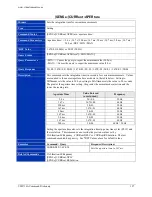
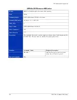
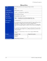
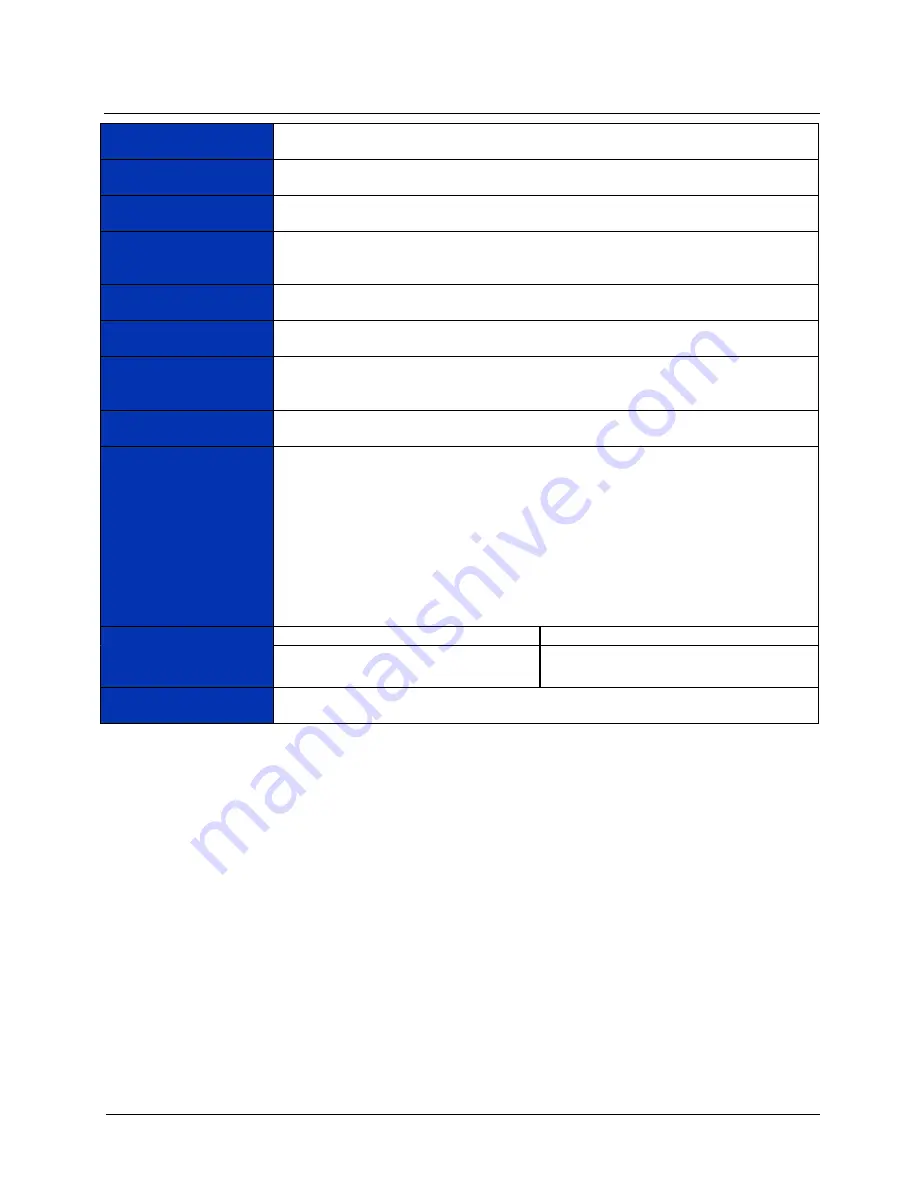
[SENSe:]RESistance:RESolution 

Purpose 

Selects the resolution for the resistance measurements 


Type 

Setting 


Command Syntax 

[SENSe:]RESistance:RESolution <resolution> 


Command Parameters 

<resolution> = 0.0001 | 0.001 | 0.01 | 0.1 | 1 | 10 | 100 | 1000 | DEF | MIN | MAX 
 

Refer to the 

Resistance Specifications


*RST Value 

Autoranging 


Query Syntax 

[SENSe:]RESistance:RESolution? [<MIN | MAX>] 


Query Parameters 

<MIN> 

= Causes the query to report the minimum value (0.0001 Ω) 

<MAX> 

= Causes the query to report the maximum value (1000 Ω)


Query Response 

0.0001 | 0.001 | 0.01 | 0.1 | 1 | 10 | 100 | 1000 


Description 

This command sets the resolution for resistance measurements.  MINimum sets the 
value to 100 

µ

Ω; MAXimum sets the value to 1 kΩ. 

 
Setting resolution also sets the aperture time and the integration time in power line 
cycles.  This command can override the previous values set by RESistance:APERture or 
RESistance:NPLC.  The last command executed has priority. 


Examples 

Command / Query 

Response (Description) 


RES:RES 0.001 

(

Sets the resolution to 1 mΩ.) 


Related Commands 

[SENSe:]RESistance:APERture 
[SENSe:]RESistance:NPLC 


Summary of Contents for VM2710A

Page 1: ...bus VM2710A 6 5 DIGIT MULTIMETER USER S MANUAL P N 82 0032 000 Revised February 7 2013 VTI Instruments Corp 2031 Main Street Irvine CA 92614 6509 949 955 1894 ...

Page 2: ...ting the Chassis Backplane Jumpers 21 Setting the Logical Address 22 Front Panel Interface Wiring 23 SECTION 3 24 PROGRAMMING 24 Introduction 24 Notation 26 Register Access 26 Register Access Programming Example 30 CALIBRATION 34 Calibration Commands 34 MFGTEST Commands 37 SECTION 4 40 COMMAND DICTIONARY 40 Introduction 40 Alphabetical Command Listing 40 Command Dictionary 46 IEEE 488 2 COMMON COM...

Page 3: ...ONVert OFFSet CURRent DC 80 CALibration CONVert OFFSet FRESistance 81 CALibration CONVert OFFSet RESistance 82 CALibration CONVert OFFSet VOLTage AC 83 CALibration CONVert OFFSet VOLTage DC 84 CALibration DEFault 85 CALibration LFRequency 86 CALibration NUMBer 87 CALibration RESet 88 CALibration SECure CODE 89 CALibration SECure STATe 90 CALibration STORe 91 CALibration ZERO 92 CALibration ZERO UP...

Page 4: ... AUTOmatic 139 SENSe RESistance RANGe DELay AUTOmatic 140 SENSe RESistance RESolution 141 SENSe VOLTage AC RANGe 142 SENSe VOLTage APERture 143 SENSe VOLTage DC RANGe 144 SENSe VOLTage NPLC 145 SENSe VOLTage RANGe AUTOmatic 146 SENSe VOLTage RANGe DELay AUTOmatic 147 SENSe VOLTage RESolution AC 148 SENSe VOLTage RESolution DC 149 TEST 150 TRACe FEED 151 TRIGger BUFFered 152 TRIGger COUNt 153 TRIGg...

Page 5: ...ing charges duties and taxes for products returned to VTI from another country VTI warrants that its software and firmware designated by VTI for use with a product will execute its programming when properly installed on that product VTI does not however warrant that the operation of the product or software or firmware will be uninterrupted or error free LIMITATION OF WARRANTY The warranty shall no...

Page 6: ...e 93 68 EEC and carries the CE mark accordingly The product has been designed and manufactured according to the following specifications SAFETY EN61010 2001 EMC EN61326 1997 w A1 98 Class A CISPR 22 1997 Class A VCCI April 2000 Class A ICES 003 Class A ANSI C63 4 1992 AS NZS 3548 w A1 A2 97 Class A FCC Part 15 Subpart B Class A EN 61010 1 2001 The product was installed into a C size VXI mainframe ...

Page 7: ...r in this manual WARNING Indicates that a procedure or condition may cause bodily injury or death CAUTION Indicates that a procedure or condition could possibly cause damage to equipment or loss of data These symbols may appear on the product ATTENTION Important safety instructions Frame or chassis ground WARNINGS Follow these precautions to avoid injury or damage to the product Use Proper Power C...

Page 8: ...oid electric shock the grounding conductor must be connected to earth ground Operating Conditions To avoid injury electric shock or fire hazard Do not operate in wet or damp conditions Do not operate in an explosive atmosphere Operate or store only in specified temperature range Provide proper clearance for product ventilation to prevent overheating DO NOT operate if any damage to this product is ...

Page 9: ...ner Road Suite 13 Valley View OH 44125 Phone 216 447 8950 Fax 216 447 8951 VTI Instruments Lake Stevens Instrument Division 3216 Wetmore Avenue Suite 1 Everett WA 98201 Phone 949 955 1894 Fax 949 955 3041 VTI Instruments Pvt Ltd Bangalore Instrument Division 642 80 Feet Road Koramangala IV Block Bangalore 560 034 India Phone 91 80 4040 7900 Phone 91 80 4162 0200 Fax 91 80 4170 0200 Technical Suppo...

Page 10: ...Platform family This gives the user the added flexibility of combining it with other instruments such as arbitrary waveform generators or digitizers to create a multi function C size card Finally users do not need to take up a complete VXIbus card slot for the DMM functionality required making the VM2710A the ideal choice for data acquisition and ATE The VM2710A may be combined with any of the oth...

Page 11: ...sting or precision measurements Measurement aperture times may be programmed allowing the choice of resolution accuracy and noise rejection i e rejection of 50 Hz or 60 Hz noise Fast function range changes allow for optimum measurement throughput Short aperture times give high speed readings while longer aperture times give greater accuracy The DMM has extensive triggering capabilities including p...

Page 12: ...for current function DATA ACCESS TYPES Register or message based word serial MEMORY 64 000 readings 256 000 readings optional CALIBRATION METHOD Programmable with covers on calibration constants stored in non volatile memory OVERLOAD INDICATION Programmable AUTORANGING Up Ranges Down Ranges 120 of range in dc volts ac volts and current functions 100 of range in ohms function 10 of range in dc volt...

Page 13: ... mV 1 mV 10 mV 24 HR ACCURACY READING RANGE TCAL 1 C AFTER 1 HR WARM UP Range 100 PLC 6 5 Digits 10 PLC 6 5 Digits 1 PLC 5 5 Digits 0 1 PLC 5 5 Digits 0 03 PLC 4 5 Digits 0 1 V 0 001 0 002 0 001 0 002 0 001 0 002 0 001 0 005 0 01 0 01 1 0 V 0 001 0 001 0 001 0 001 0 001 0 001 0 001 0 003 0 01 0 01 10 0 V 0 001 0 001 0 001 0 001 0 001 0 001 0 001 0 003 0 01 0 01 100 0 V 0 001 0 001 0 001 0 001 0 00...

Page 14: ...0 005 0 007 0 005 0 007 0 005 0 007 0 009 0 03 0 02 1 0 V 0 005 0 005 0 005 0 005 0 005 0 005 0 005 0 007 0 03 0 02 10 0 V 0 007 0 005 0 007 0 005 0 007 0 005 0 007 0 007 0 03 0 02 100 0 V 0 008 0 005 0 008 0 005 0 008 0 005 0 010 0 007 0 03 0 02 300 0 V 0 008 0 005 0 008 0 005 0 008 0 005 0 010 0 006 0 03 0 02 TEMPERATURE COEFFICIENT 0 C 18 C AND 28 C 55 C READING RANGE C 0 1 V 1 0 V 10 0 V 100 0...

Page 15: ... 0 001 0 005 0 001 0 005 0 005 0 010 0 010 1 0 A 0 005 0 005 0 005 0 005 0 005 0 005 0 005 0 005 0 010 0 010 90 DAY ACCURACY READING RANGE TCAL 5 C AFTER 1 HR WARM UP AND DC ZERO COMMAND Range 100 PLC 6 5 Digits 10 PLC 6 5 Digits 1 PLC 5 5 Digits 0 1 PLC 5 5 Digits 0 03 PLC 4 5 Digits 10 mA 0 015 0 010 0 015 0 010 0 015 0 010 0 015 0 010 0 030 0 050 100 mA 0 015 0 004 0 015 0 004 0 015 0 004 0 015...

Page 16: ...V 1 mV 1 mV 1 mV 10 mV 10 mV 300 0 V 1 mV 1 mV 1 mV 10 mV 10 mV ACCURACY 100 10 AND 1 PLC FOR 24 HR TCAL 1 C AFTER 1 HR WARM UP READING RANGE SINE WAVE INPUT 5 FULL SCALE F S LOW FREQUENCY FILTER ON Range 0 1 V Range 1 0 V 300 0 V Ranges VIN x Freq 1 5x10⁷ 20 Hz 30 Hz 1 00 0 15 1 00 0 02 30 Hz 50 Hz 0 50 0 15 0 50 0 02 50 Hz 200 Hz 0 20 0 15 0 20 0 02 200 Hz 10 kHz 0 05 0 15 0 02 0 02 10 kHz 50 kH...

Page 17: ...5 1 12 0 04 30 Hz 50 Hz 0 57 0 15 0 57 0 04 50 Hz 200 Hz 0 25 0 15 0 25 0 04 200 Hz 10 kHz 0 10 0 15 0 07 0 04 10 kHz 50 kHz 0 25 0 15 0 12 0 06 50 kHz 100 kHz 0 75 0 25 0 45 0 20 100 kHz 300 kHz 4 00 0 60 4 00 0 60 TEMPERATURE COEFFICIENT 0 C 18 C AND 28 C 55 C READING RANGE C 20 Hz 30 Hz 30 Hz 50 Hz 50 Hz 200 Hz 200 Hz 10 kHz 10 kHz 50 kHz 50 kHz 100 kHz 0 020 0 001 0 010 0 001 0 005 0 001 0 005...

Page 18: ...00 0 20 1 00 0 04 1 00 0 20 30 Hz 50 Hz 0 50 0 20 0 50 0 04 0 50 0 20 50 Hz 1k Hz 0 20 0 20 0 20 0 04 0 20 0 20 1k Hz 5kHz 0 17 0 20 0 17 0 20 0 17 0 20 5kHz 10kHz 0 55 0 30 0 55 0 30 3 0 0 30 90 DAY ACCURACY 2 Range 10 mA Range 100 mA Range 1 0 A Range 20 Hz 30 Hz 1 10 0 20 1 10 0 05 1 10 0 20 30 Hz 50 Hz 0 60 0 20 0 60 0 05 0 60 0 20 50 Hz 1kHz 0 30 0 20 0 30 0 05 0 30 0 20 1kHz 5kHz 0 27 0 20 0...

Page 19: ... 6 5 Digits 1 PLC 5 5 Digits 0 1 PLC 5 5 Digits 0 03 PLC 4 5 Digits 20 Ω 100 µΩ 100 µΩ 100 µΩ 1 mΩ 1 mΩ 200 Ω 100 µΩ 1 mΩ 1 mΩ 10 mΩ 10 mΩ 2 kΩ 1 mΩ 1 mΩ 10 mΩ 100 mΩ 100 mΩ 20 kΩ 10 mΩ 10 mΩ 100 mΩ 1 0 Ω 1 0 Ω 200 kΩ 100 mΩ 100 mΩ 1 0 Ω 10 Ω 10 Ω 2 MΩ 1 0 Ω 1 0 Ω 10 Ω 100 Ω 100 Ω 20 MΩ 100 Ω 100 Ω 1 kΩ 1 kΩ 1 kΩ 4 WIRE 24 HOUR ACCURACY READING RANGE TCAL 1 C AFTER 1 HOUR WARM UP 3 Range 100 PLC 1...

Page 20: ...3 0 03 200 kΩ 0 010 0 005 0 010 0 005 0 010 0 007 0 010 0 007 0 03 0 03 2 MΩ 0 015 0 005 0 015 0 005 0 015 0 010 0 060 0 010 0 05 0 04 20 MΩ 0 025 0 005 0 025 0 005 0 025 0 010 0 210 0 010 0 22 0 05 TEMPERATURE COEFFICIENT 0 C 18 C AND 28 C 55 C READING RANGE C Range 20 Ω 200 Ω 2 kΩ 20 kΩ 200 kΩ 2 MΩ 20 MΩ 0 0007 0 0002 0 0007 0 0002 0 0006 0 0001 0 0006 0 0002 0 0006 0 0002 0 0015 0 0004 0 0035 0...

Page 21: ... configured prior to the VM2710A s installation CALCULATING SYSTEM POWER AND COOLING REQUIREMENTS It is imperative that the chassis provide adequate power and cooling for this module Referring to the chassis user s manual confirm that the power budget for the system the chassis and all modules installed therein is not exceeded and that the cooling system can provide adequate airflow at the specifi...

Page 22: ...s as required by the VXIbus specification revisions 1 3 and 1 4 The logical address of the instrument is set on the VMIP carrier The VMIP logical addresses must be set to an even multiple of 4 unless dynamic addressing is used Switch positions 1 and 2 must always be set to the OFF position Therefore only addresses of 4 8 12 16 252 are allowed The address switch should be set for one of these legal...

Page 23: ...ment the module will have three A channels and three B channels TABLE 2 1 DIGIT MULTIMETER PIN OUTS PIN NUMBER SIGNAL 1 FRONT PANEL TRIGGER INPUT 2 GUARD CHAN B Shield 3 INPUT CHAN B LOW 4 INPUT CHAN B HIGH 5 GUARD CHAN B Shield 6 INPUT CHAN A LOW 7 INPUT CHAN A HIGH 8 GUARD CHAN A Shield 9 GROUND 10 GUARD CHAN B Shield 11 I CHAN B ac dc current and 4 wire ohms 12 I CHAN B ac dc current and 4 wire...

Page 24: ...llows TRIGger DELay AUTOmatic SLOPe POS SOURce EXT The above command is the same as the these three commands TRIGger DELay AUTOmatic TRIGger SLOPe POS TRIGger SOURce EXT See the Standard Command for Programmable Instruments SCPI Manual Volume 1 Syntax Style Section 6 for more information The SCPI commands in this section are listed in upper and lower case Character case is used to indicate differe...

Page 25: ... data is used for a parameter both short and long forms are recognized If the command has a query form with character response data the short form is always returned in upper case As an example to find out what the current trigger source setting is use the following command TRIG SOUR The response would be EXT This tells the user that the trigger is set to an external source Multiple commands can a...

Page 26: ... the information as a 32 bit data value with data high and data low retrieved from two 16 bit locations The second method is 32 bit access from one 16 bit location with the data high data low information alternating data high is first This second method of data retrieval must be properly synchronized otherwise the data would all be offset by 16 bits The register map is specified in Table 3 2 The e...

Page 27: ... 6 0x00000000 12 200 Ω 2 50000e 5 0x00000000 13 2 kΩ 2 50000e 4 0x00000000 14 20 kΩ 2 50000e 3 0x00000000 15 200 kΩ 2 50000e 2 0x00000000 16 2 MΩ 2 50000e 1 0x00000000 17 20 MΩ 2 50000e 0 0x00000000 18 20 4 Wire Ω 2 50000e 6 0x00000000 19 200 4 Wire Ω 2 50000e 5 0x00000000 20 2 k 4 Wire Ω 2 50000e 4 0x00000000 21 20 k 4 Wire Ω 2 50000e 3 0x00000000 22 200 k 4 Wire Ω 2 50000e 2 0x00000000 23 2 M 4 ...

Page 28: ...ADDRESS SPACE Offset Description 3E 3C 3A 38 36 34 32 30 2E Write Pointer Low 2C Write Pointer High 2A Read Pointer Low 28 Read Pointer High 26 Data 16 Bit 24 FIFO Status 22 Data Low 32 Bit 20 Data High 32 Bit 1E 1C 1A 18 16 A32 Pointer Low 14 A32 Pointer High 12 A24 Pointer Low 10 A24 Pointer High E Data Low C Data High A Response Data Extended 8 Protocol Signal Register 6 Offset Register 4 Statu...

Page 29: ...asn t been a data underflow Once set stays set until a RST 1 Data overflow data wasn t read out of the FIFO fast enough and the FIFO overflowed 0 There hasn t been a FIFO overflow Once set stays set until a RST DATA 16 high low indicator 1 Data read from the DATA 16 register is the high 16 bits 0 Data read from the DATA 16 register is the low 16 bits FIFO size 1 256 k readings deep 0 64 k readings...

Page 30: ...ic char reg_base int main static INT16 addr 9 static UINT32 i window value static INT32 int_value static NIVXI_STATUS ret static double delta_time del_time static UINT8 buf 100 Register access variables static UINT16 data_hi data_lo temp Cls Initialize the library ret InitVXIlibrary Put in a known state vxiwrt addr rst vxiwrt addr conf volt dc 10 vxiwrt addr volt nplc 1 Ask the instrument how big ...

Page 31: ...pc buf Find out how much time it took for the triggers delta_time Timer delta_time printf Time spent triggering f seconds n delta_time Map the A16 address space into our space for quick register access reg_base char MapVXIAddress 1 0 1000 window ret 0xc000 addr 0x40 Initialize two pointers for easy access data_hi INT16 reg_base 0x0020 data_lo INT16 reg_base 0x0022 Initialize some variables for mea...

Page 32: ...ultiply by the scale factor Gather the statistics high low and average accumulate accumulate volt if volt voltmin voltmin volt if volt voltmax voltmax volt Keep track of how many readings we read i Find out how much time it took to get the readings delta_time Timer delta_time Compute the average accumulate accumulate i Print the information printf Count d on s at s Elapsed time f seconds n i DateS...

Page 33: ...ng 33 printf Min delta f Max delta f Delta hi to lo f n accumulate voltmin voltmax accumulate voltmax voltmin Return the mapping window to the system ret UnMapVXIAddress window Close the library ret CloseVXIlibrary Exit with no error return 0 ...

Page 34: ...currently set range and function CALibration CONVert GAIN CURRent AC Reports the gain for a specified range in the ac Current function See the Scale column in Table 3 1 Function and Range CALibration CONVert GAIN CURRent DC Reports the gain for a specified range in the dc current function See the Scale column in Table 3 1 Function and Range CALibration CONVert GAIN FRESistance Reports the gain for...

Page 35: ...FFSet VOLTage AC Reports the offset for a specified range in the ac voltage function See the Offset column in Table 3 1 Function and Range CALibration CONVert OFFSet VOLTage DC Reports the offset for a specified range in the dc voltage function See the Offset column in Table 3 1 Function and Range CALibration DEFault This command sets the Gain and Offset values to their respective default values T...

Page 36: ...is command query CALibration SECure STATe This command disables or enables the Calibration Secure state This command is NOT dependant on any other settings on the VM2710A other than the CALibration SECure CODE This command is performed by the driver function vtvm2710_enableDisableSecState CALibration STORe This command stores the currently loaded calibration values into Non volatile memory Before ...

Page 37: ... SCALE register in the converter where S is the value to be set and is only on the Aperture setting MFGTEST 2 H0120 This command writes to the COMMAND register in the converter MFGTEST 2 addr Read a Flash byte used to read headers MFGTEST 4 F This command writes to the ac DAC where F is a value between 1 and 128 The equivalent command is MFGTEST ACDAC F MFGTEST 4 Reports the ac DAC value The equiv...

Page 38: ...ent in the set aperture MFGTEST 11 L Reports the linearization slope value MFGTEST 12 L C Sets a linearization offset There are 16 linearization constants 0 15 for each aperture setting L indicates which linearization segment is being set and C is the constant to be loaded for the selected linearization segment in the set aperture MFGTEST 12 L Reports the linearization offset value MFGTEST 15 coun...

Page 39: ...he 340 processor linearization is ON MFGTEST 23 Reports if the 340 processor linearization is ON 1 or OFF 0 MFGTEST 30 Read the CAL register in the converter MFGTEST 31 Read the SCALE register in the converter MFGTEST 32 boolean Set to 0 the 251 processor linearization is OFF set to 1 the 251 processor linearization is ON MFGTEST 32 Read the 251 main header pointer can be used to get the file revi...

Page 40: ...user in the use of each command Every command entry describes the exact command and or query syntax the use and range of parameters and a description of the command s purpose ALPHABETICAL COMMAND LISTING The following tables provide an alphabetical listing of each command supported by the VM2710A along with a brief definition If an X is found in the column titled RST then the value or setting cont...

Page 41: ... ESR Query the Standard Event Status Register N A IDN Query the module identification string N A OPC Set the OPC bit in the Event Status Register N A RST Resets the module to a known state N A SRE Set the service request enable register N A STB Query the Status Byte Register N A TRG Causes a trigger event to occur N A TST Starts and reports a self test procedure N A WAI Halts execution and queries...

Page 42: ...tion CONVert GAIN VOLTage DC Reports dc voltage gain N A CALibration CONVert OFFSet Reports current function offset N A CALibration CONVert OFFSet CURRent AC Reports ac current offset N A CALibration CONVert OFFSet CURRent DC Reports dc current offset N A CALibration CONVert OFFSet FRESistance Reports 4 wire ohms offset N A CALibration CONVert OFFSet RESistance Reports 2 wire ohms offset N A CALib...

Page 43: ... function X Autoranging 1 PLC MEASure VOLTage DC Selects the dc voltage function X Autoranging 1 PLC MFGTEST 99 Enables or disables the ohms current function X 1 OUTPut TTLTrg Selects the a specified VXIbus trigger line 0 7 X 0 lines 0 7 off OUTPut TTLTrg POLarity Sets the output signal polarity X NEG RANGe AUTOmatic Enables the autoranging function X 1 RANGe DELay Sets the delay settling time aft...

Page 44: ... the range for ac voltage measurements X Autoranging SENSe VOLTage APERture Sets the integration time for voltage measurements X 1 67E 02 60 Hz or 2E 02 50 Hz SENSe VOLTage DC RANGe Selects the range for dc voltage measurements X Autoranging SENSe VOLTage NPLC Sets the integration time in Power Line Cycles PLCs X 1 SENSe VOLTage RANGe AUTOmatic Enables disables the autorange function X 1 SENSe VOL...

Page 45: ...Ration EVENt Queries the Operation Status Event Register X STATus PRESet Presets the Status Register X STATus QUEStionable CONDition Queries the Questionable Status Condition Register X STATus QUEStionable ENABle Sets the Questionable Status Enable Register X STATus QUEStionable EVENt Queries the Questionable Status Event Register X SYSTem ERRor Queries the Error Queue X Clears queue SYSTem VERsio...

Page 46: ... their legal range Reset Value Describes the values assumed when the RST command is sent Query Syntax Details the exact query form of the command Query Parameters Describes the parameters sent with the command and their legal range The default parameter values are assumed the same as in the command form unless described otherwise Query Response Describes the format of the query response and the va...

Page 47: ...arameters N A RST Value N A Query Syntax N A Query Parameters N A Query Response N A Description This command clears the Status Event Register Operation Status Register and the Questionable Data Signal Register It also clears the OPC flag and clears all queues except the output queue Examples Command Query Response Description CLS Clears all status and event registers Related Commands N A ...

Page 48: ...omplete description of the ESE register A value of 1 in a bit position of the ESE register enables generation of the ESB Event Status Bit in the Status Byte by the corresponding bit in the ESR If the ESB is set in the SRE register then an interrupt will be generated See the ESR command for details regarding the individual bits The ESE register layout is Bit 0 Operation Complete Bit 1 Request Contr...

Page 49: ...4 Execution Error Bit 5 Command Error Bit 6 User Request Bit 7 Power On The Operation Complete bit is set when it receives an OPC command The Query Error bit is set when data is over written in the output queue This could occur if one query is followed by another without reading the data from the first query The Execution Error bit is set when an execution error is detected Errors that range from ...

Page 50: ...ation string of the module The response is divided into four fields separated by commas The first field is the manufacturer s name the second field is the model number the third field is an optional serial number and the fourth field is the firmware revision number If a serial number is not supplied the third field is set to 0 zero Examples Command Query Response Description IDN VTI Instruments VM...

Page 51: ... RST Value N A Query Syntax OPC Query Parameters N A Query Response 1 Description The Operation Complete command sets the OPC bit in the Event Status Register when all pending operations have completed The Operation Complete query will return a 1 to the output queue when all pending operations have completed Examples Command Query Response Description OPC OPC 1 Related Commands WAI ...

Page 52: ...ntax RST Command Parameters N A RST Value N A Query Syntax N A Query Parameters N A Query Response N A Description The Reset command resets the module s hardware and software to a known state See the command index at the beginning of this chapter for the default parameter values used with this command Examples Command Query Response Description RST Related Commands N A ...

Page 53: ...ane interrupts If a bit is set in the mask that newly enables a bit set in the status byte and interrupts are enabled the module will generate a REQUEST TRUE event via an interrupt See the STB Command for the layout of bits Note Bit 6 is always internally cleared to zero as required by IEEE 488 2 section 11 3 2 3 The layout of the Service Request Enable Register is Bit 0 Unused Bit 1 Unused Bit 2 ...

Page 54: ...ption The Read Status Byte query fetches the current contents of the Status Byte Register See the IEEE 488 2 specification for additional information regarding the Status byte Register and its use The layout of the Status Register is Bit 0 Unused Bit 1 Unused Bit 2 Error Queue Has Data Bit 4 Questionable Status Summary not used Bit 5 Message Available Bit 6 Master Summary Status Bit 7 Operation St...

Page 55: ...t to occur Type IEEE 488 2 Common Command Command Syntax TRG Command Parameters N A RST Value N A Query Syntax N A Query Parameters N A Query Response N A Description The Trigger command causes a trigger event to occur Examples Command Query Response Description TRG Related Commands N A ...

Page 56: ...ponse Numeric ASCII value from 0 to 143 Description The Self Test query causes the VM2710A to run its self test procedures and report on the results A value of 0 means there were no errors all tests passed A non zero value is composed of the following 1 Non volatile memory test failure 2 FPGA data path failure 4 Internal resistance measurement failure The value returned is the sum of all failures ...

Page 57: ...rs N A RST Value N A Query Syntax N A Query Parameters N A Query Response N A Description The Wait to Continue command halts the execution of commands and queries until the No Operation Pending message is true This command makes sure that all previous commands have been executed before proceeding It provides a way of synchronizing the module with its commander Examples Command Query Response Descr...

Page 58: ...ORt command removes the VM2710A from the wait for trigger state and places it in the idle state This command can only be used when the trigger source is set to BUS or HOLD ABORt does not affect any other settings When the INITiate command is sent the trigger system will respond as it did before When the trigger source is set to BUS or HOLD the ABORt command places the VM2710A in idle state Subsequ...

Page 59: ...Description Queries and reports the highest reading value that has been taken The CALCulate FUNCtion must first be set to AVERage Examples Command Query Response Description CALC AVER Sets the calculate function to keep track on reading averages CALC AVER MAX Reports the highest reading value Related Commands CALCulate FUNCtion AVERage AVERage CALCulate FUNCtion AVERage COUNt CALCulate FUNCtion AV...

Page 60: ...er Description Queries and reports the lowest reading that has been taken The CALCulate FUNCtion must first be set to AVERage Examples Command Query Response Description CALC FUNC AVER Sets the calculate function to keep track of reading averages CALC AVER MIN Reports the lowest reading value Related Commands CALCulate FUNCtion AVERage AVERage CALCulate FUNCtion AVERage COUNt CALCulate FUNCtion AV...

Page 61: ...uery Syntax CALCulate FUNCtion Query Parameters N A Query Response AVER LIM NULL Description This command sets the calculate function to either AVERage LIMit or NULL The reset value is NULL Examples Command Query Response Description CALC FUNC AVER Sets the calculate function to keep track of reading averages Related Commands CALCulate FUNCtion AVERage CALCulate FUNCtion LIMit CALCulate FUNCtion N...

Page 62: ... taken divided by the number of reading counts Description Queries and reports the average reading taken The CALCulate FUNCtion must first be set to AVERage Examples Command Query Response Description CALC AVER Sets the calculate function to keep track of readings averages CALC AVER AVER readings sum readings count Reports the average reading taken Related Commands CALCulate FUNCtion AVERage COUNt...

Page 63: ... VM2701A has been CALCulate FUNCtion AVERage mode Description Queries and reports the reading count the number of readings that have been taken The CALCulate FUNCtion must first be set to AVERage Examples Command Query Response Description CALC AVER Sets the calculate function to keep track of reading averages CALC COUN Reports the reading count Related Commands CALCulate FUNCtion AVERage AVERage ...

Page 64: ...ription This command sets the lower reading limit for the current function and range If a measurement is below this set limit the limit low failure bit would be set in the Status Questionable register Limit Low Failure 0x0800 Limit Low Failure Pulse 0x2000 Examples Command Query Response Description CALC LIM LOW 3 5 Sets the lower limit to 3 5 V in the 10 V range CALC LIM LOW LAST Sets the lower l...

Page 65: ...ONE Query Syntax CALCulate FUNCtion LIMit LOWer TTLTrg Query Parameters N A Query Response 0 1 2 3 4 5 6 7 NONE Description This command enables the below limit failure to also be read off one of the backplane trigger lines 0 7 The default value is NONE Examples Command Query Response Description CALC LIM LOW TTLT 3 Enables the below limit failure to be captured from the backplane trigger line 3 R...

Page 66: ...iption This command sets the upper reading limit for the current function and range If a measurement is above this set limit the limit high failure bit would be set in the Status Questionable register Limit High Failure 0x1000 Limit High Failure Pulse 0x4000 Examples Command Query Response Description CALC LIM UPP 8 8 Sets the upper limit to 8 8 V in the 10 V range CALC LIM UPP LAST Sets the upper...

Page 67: ...ONE Query Syntax CALCulate FUNCtion LIMit UPPer TTLTrg Query Parameters N A Query Response 0 1 2 3 4 5 6 7 NONE Description This command enables the above limit failure to also be read off one of the backplane trigger lines 0 7 The default value is NONE Examples Command Query Response Description CALC LIM UPP TTLT 3 Enables the above limit failure to be captured from the backplane trigger line 3 R...

Page 68: ...alue Command Parameters value number MAXimum MINimum LAST RST Value 0 Query Syntax CALCulate FUNCtion NULL OFFSet Query Parameters N A Query Response number Description Sets the calculate offset value The default value is zero 0 Examples Command Query Response Description CALC NULL OFFS LAST Sets the last measurement value as the offset value Related Commands CALCulate FUNCtion ...

Page 69: ...Query Syntax CALCulate NORead Query Parameters N A Query Response 0 1 Description The Calculate NoRead command sets the instrument such that a read only returns the calculation values rather than returning all data The default setting is OFF 0 which returns all data when a read is made Examples Command Query Response Description CALC NOR 1 Sets the instrument to only return the calculate values Re...

Page 70: ...and Syntax CALCulate STATe boolean Command Parameters boolean 0 1 OFF ON RST Value 0 Query Syntax CALCulate STATe Query Parameters N A Query Response 0 1 Description This command enables or disables the calculate function Examples Command Query Response Description CALC STAT 1 Enables the calculate function Related Commands CALCulate FUNCtion ...

Page 71: ...he VM2710A See the Scale column in Table 3 1 Function and Range Calibration commands should only be executed by qualified personnel Changing these values incorrectly can cause the instrument to perform improperly Examples Command Query Response Description CONV GAIN Queries and reports the gain for the current function and range setting Related Commands CALibration CONVert GAIN CURRent AC CALibrat...

Page 72: ...pecified range in the ac Current function See the Scale column in Table 3 1 Function and Range Calibration commands should only be executed by qualified personnel Changing these values incorrectly can cause the instrument to perform improperly Examples Command Query Response Description CAL CONV GAIN CURR AC 1 Queries and reports the gain for the 1 A range Related Commands CALibration CONVert GAIN...

Page 73: ...ified range in the dc current function See the Scale column in Table 3 1 Function and Range Calibration commands should only be executed by qualified personnel Changing these values incorrectly can cause the instrument to perform improperly Examples Command Query Response Description CAL CONV GAIN CURR DC 1 Qureies and reports the gain for the 1 A range Related Commands CALibration CONVert GAIN CA...

Page 74: ... gain for a specified range in the 4 wire ohms function See the Scale column in Table 3 1 Function and Range Calibration commands should only be executed by qualified personnel Changing these values incorrectly can cause the instrument to perform improperly Examples Command Query Response Description CAL CONV GAIN FRES 20000 Queries and reports the gain for the 20 kΩ range Related Commands CALibra...

Page 75: ...n for a specified range in the 2 wire ohms function See the Scale column in Table 3 1 Function and Range Calibration commands should only be executed by qualified personnel Changing these values incorrectly can cause the instrument to perform improperly Examples Command Query Response Description CAL CONV GAIN RES 20000 Qureies and reports the gain for the 20 kΩ range Related Commands CALibration ...

Page 76: ...in for a specified range in the ac voltage function See the Scale column in Table 3 1 Function and Range Calibration commands should only be executed by qualified personnel Changing these values incorrectly can cause the instrument to perform improperly Examples Command Query Response Description CAL CONV GAIN VOLT AC 10 Queries and reports the gain for the 10 V range Related Commands CALibration ...

Page 77: ...for a specified range in the dc voltage function See the Scale column in Table 3 1 Function and Range Calibration commands should only be executed by qualified personnel Changing these values incorrectly can cause the instrument to perform improperly Examples Command Query Response Description CAL CONV GAIN VOLT DC 10 Queries and reports the gain for the 10 V range Related Commands CALibration CON...

Page 78: ...e VM2710A See the Offset column in Table 3 1 Function and Range Calibration commands should only be executed by qualified personnel Changing these values incorrectly can cause the instrument to perform improperly Examples Command Query Response Description CONV OFFS Queires and reports the offset for the current function and range setting Related Commands CALibration CONVert OFFSet CURRent AC CALi...

Page 79: ...ed range in the ac Current function See the Offset column in Table 3 1 Function and Range Calibration commands should only be executed by qualified personnel Changing these values incorrectly can cause the instrument to perform improperly Examples Command Query Response Description CAL CONV OFFS CURR AC 1 Queires and reports the offset for the 1 A range Related Commands CALibration CONVert OFFSet ...

Page 80: ...fied range in the dc current function See the Offset column in Table 3 1 Function and Range Calibration commands should only be executed by qualified personnel Changing these values incorrectly can cause the instrument to perform improperly Examples Command Query Response Description CAL CONV OFFS CURR DC 1 Queries and reports the offset for the 1 A range Related Commands CALibration CONVert OFFSe...

Page 81: ... for a specified range in the 4 wire ohms function See the Offset column in Table 3 1 Function and Range Calibration commands should only be executed by qualified personnel Changing these values incorrectly can cause the instrument to perform improperly Examples Command Query Response Description CAL CONV OFFS FRES 20000 Queries and reports the gain for the 20 kΩ range Related Commands CALibration...

Page 82: ...t for a specified range in the 2 wire ohms function See the Offset column in Table 3 1 Function and Range Calibration commands should only be executed by qualified personnel Changing these values incorrectly can cause the instrument to perform improperly Examples Command Query Response Description CAL CONV OFFS RES 20000 Queries and reports the gain for the 20 kΩ range Related Commands CALibration...

Page 83: ... a specified range in the ac voltage function See the Offset column in Table 3 1 Function and Range Calibration commands should only be executed by qualified personnel Changing these values incorrectly can cause the instrument to perform improperly Examples Command Query Response Description CAL CONV OFFS VOLT AC 10 Queries and reports the gain for the 10 V range Related Commands CALibration CONVe...

Page 84: ...for a specified range in the dc voltage function See the Offset column in Table 3 1 Function and Range Calibration commands should only be executed by qualified personnel Changing these values incorrectly can cause the instrument to perform improperly Examples Command Query Response Description CAL CONV OFFS VOLT DC 10 Queries and reports the gain for the 10 V range Related Commands CALibration CO...

Page 85: ...ery Syntax N A Query Parameters N A Query Response N A Description The Calibration Default command sets all the calibration gain and offset values to their respective default values Calibration commands should only be executed by qualified personnel Changing these values incorrectly can cause the instrument to perform improperly Examples Command Query Response Description CAL DEF Related Commands ...

Page 86: ...ides normal mode rejection of power line related noise MINimum Selects 50 Hz line frequency reference MAXimum Selects 60 Hz line frequency reference This command set can be overridden by a 50 Hz or 60 Hz aperture time set the last command executed has priority The RST command has no affect on this setting since it is stored in non volatile memory The query will report the current frequency setting...

Page 87: ...0 to 32 767 Description The Calibration Number query reports the number of times the multimeter has been calibrated in a decimal value The number is sent to the output buffer The calibration number is stored in non volatile memory and is not affected by a reset command Calibration commands should only be executed by qualified personnel Changing these values incorrectly can cause the instrument to ...

Page 88: ... Query Response N A Description This command will load the Calibration DACs from the calibration constants stored in non volatile memory This allows the user to modify Calibration DAC values with the ability to restore the original values Calibration commands should only be executed by qualified personnel Changing these values incorrectly can cause the instrument to perform improperly Examples Com...

Page 89: ...gth arbitrary block format RST Value N A Query Syntax CALibration SECure CODE Query Parameters N A Query Response Description Calibration security must first be disabled before the code can be changed Before shipping the instrument the factory sets the code to VM2710 Calibration commands should only be executed by qualified personnel Changing these values incorrectly can cause the instrument to pe...

Page 90: ... the state on or off In order to disable the security state the current security code must be supplied To turn on security code does not need to be supplied If it is supplied the code is checked The security code must be supplied in IEEE 488 2 definite or indefinite length arbitrary block format Calibration commands should only be executed by qualified personnel Changing these values incorrectly c...

Page 91: ... Value N A Query Syntax N A Query Parameters N A Query Response N A Description The Calibration Secure State must be disabled before initiating a Calibration Store command Calibration commands should only be executed by qualified personnel Changing these values incorrectly can cause the instrument to perform improperly Examples Command Query Response Description CAL STOR Related Commands CALibrati...

Page 92: ... will take a zero measurement for each of the voltage ranges thus taking more time Note that this command can only be issued for DC voltages and can only be run when the aperture is set to at least 1 PLC Also note that if the resolution is set to 1x10 6 V or more by the CONF VOLT the CAL ZERO command will not work unless the user manual adjusts the aperture to 1 PLC Calibration commands should onl...

Page 93: ... N A Query Syntax N A Query Parameters N A Query Response N A Description Updates the current zero measurements to later be stored using the Calibration Store command Calibration commands should only be executed by qualified personnel Changing these values incorrectly can cause the instrument to perform improperly Examples Command Query Response Description CAL ZERO UPD Related Commands CALibratio...

Page 94: ...ration set be the most recent Configure or Measure command and returns these values in quotation marks Examples Command Query Response Description CONF VOLT AC 100 0 001 CONF VOLT AC 1 000000E 002 1 000000E 003 Indicates that the device is con figured for volts ac in the 100 V range at a resolution of 1 mV Related Commands CONFigure CURRent AC CONFigure CURRent DC CONFigure VOLTage AC CONFigure VO...

Page 95: ... MAXimum To input a resolution parameter a current parameter must be specified first Valid parameter combinations are no parameter a current parameter only or both a current parameter and a resolution parameter Refer to the AC Current Specificaitons in Section 1 for allowed range and resolution values The input parameters are as follows expected value 0 01 0 1 1 Specific expected current value in ...

Page 96: ...mum or MAXimum To input a resolution parameter a current parameter must be specified first Valid parameter combinations are no parameter a current parameter only or both a current parameter and a resolution parameter Refer to the DC Current Specifications in Section 1 for allowed range and resolution values The input parameters are as follows expected vlaue 0 01 0 1 1 Specific expected current val...

Page 97: ... resolution are MINimum or MAXimum To input a resolution parameter a resistance parameter must be specified first Valid parameter combinations are no parameter a resistance parameter only or both a resistance parameter and a resolution parameter Refer to the Resistance Specifications in Section 1 for allowed range and resolution values The input parameters are as follows expected value 0 Ω 20 MΩ S...

Page 98: ...s for resolution are MINimum or MAXimum To input a resolution parameter a resistance parameter must be specified first Valid parameter combinations are no parameter a resistance parameter only or both a resistance parameter and a resolution parameter Refer to the Resistance Specifications in Section 1 for allowed range and resolution values The input parameters are as follows expected value 0 Ω 20...

Page 99: ...d parameters for resolution are MINimum or MAXimum To input a resolution parameter a voltage parameter must be specified first Valid parameter combinations are no parameter a voltage parameter only or both a voltage parameter and a resolution parameter Refer to the AC Voltage Specifications in Section 1 for allowed range and resolution values The input parameters are as follows expected value 0 V ...

Page 100: ...lid parameters for resolution are MINimum or MAXimum To input a resolution parameter a voltage parameter must be specified first Valid parameter combinations are no parameter a voltage parameter only or both a voltage parameter and a resolution parameter Refer to the DC Voltage Specifications in Section 1 for allowed range and resolution values The input parameters are as follows expected value 0 ...

Page 101: ...in memory by the most recent INITiate command and places then in the output buffer The INITiate command must be executed before each FETCh query otherwise it would generate an error Each reading consists of a reading in real ASCII format If multiple readings are returned they are separated by commas A Line Feed LF and an END or Identify EOF signal follow the last reading The output format is depen...

Page 102: ...ult setting is exponential format For the decimal format the range is 0 4 0 9 i e the maximum value allowed is 4 9 Examples Command Query Response Description FORM 1 4 Sets the data format to decimal at least 1 digit before and 4 digits after the decimal FORM 15 6 4F The measurement data format is decimal but the format query still returns a C string A voltage measurement of 12 3456789 would read ...

Page 103: ...e NONE BIP UNIP Description The FORMat OVERflow command sets the format of how the user is notified of an overflow or over range NONE This is the default UNIPolar The system would return a 9 9e37 to alert the user of an overflow BIPolar The system would return a 9 9e37 for positive overflows and 9 9e37 for negative overflows Examples Command Query Response Description FORM OVER BIP Sets the overfl...

Page 104: ...Command Parameters N A RST Value Idle state Query Syntax N A Query Parameters N A Query Response N A Description This command places the multimeter in the wait for trigger state and stores the readings into memory when a trigger occurs Readings previously stored are replaced by the new ones Examples Command Query Response Description INIT Related Commands ABORt CONFigure FETCh READ ...

Page 105: ...e Setting Command Syntax INPut SOURce source Command Parameters source A B RST Value A Query Syntax INPut SOURce Query Parameters N A Query Response A B Description This command selects the input source used A or B Examples Command Query Response Description INP SOUR B INP SOUR B Related Commands N A ...

Page 106: ... OFF ON RST Value 0 Query Syntax MATH Query Parameters N A Query Response 0 1 Description The Math command turns the math function ON or OFF Examples Command Query Response Description MATH 1 Enables the math function for this module MATH 1 Indicates that the math function has been truned on Related Commands MATH FACTor MATH FACTor LAST MATH OFFSet MATH OFFSet LAST ...

Page 107: ...ers value decimal number RST Value 1 Query Syntax MATH FACTor Query Parameters N A Query Response decimal number Description This command sets the factor Value reading factor offset Math Factor LAST takes the last measured reading and sets it as the factor value Examples Command Query Response Description MATH FACT 2 MATH FACT 2 Related Commands MATH MATH OFFSet ...

Page 108: ...number RST Value 0 Query Syntax MATH OFFSet Query Parameters N A Query Response Returns the value currently set for the value parameter Description This command sets the offset Value reading factor offset Math Offset LAST takes the last measured reading and sets it as the offset value Examples Command Query Response Description MATH OFFS 1 MATH OFFS 1 Related Commands MATH MATH FACTor ...

Page 109: ...on are MINimum or MAXimum To input a resolution parameter a current parameter must be specified first Valid parameter combinations are no parameter a current parameter only or both a current parameter and a resolution parameter See the AC Current Specifications in Section 1 for allowed range and resolution values The input parameters are as follows expected value 0 01 0 1 1 Specific expected curre...

Page 110: ...solution are MINimum or MAXimum To input a resolution parameter a current parameter must be specified first Valid parameter combinations are no parameter a current parameter only or both a current parameter and a resolution parameter See the DC Current Specifications in Section 1 for allowed range and resolution values The input parameters are as follows expected value 0 01 0 1 1 Specific expected...

Page 111: ...ters for resolution are MINimum or MAXimum To input a resolution parameter a resistance parameter must be specified first Valid parameter combinations are no parameter a resistance parameter only or both a resistance parameter and a resolution parameter See the Resistance Specifications in Section 1 for allowed range and resolution values The input parameters are as follows Resistance 0 Ω 20 MΩ Sp...

Page 112: ...ameters for resolution are MINimum or MAXimum To input a resolution parameter a resistance parameter must be specified first Valid parameter combinations are no parameter a resistance parameter only or both a resistance parameter and a resolution parameter See the Resistance Specifications in Section 1 for allowed range and resolution values The input parameters are as follows Resistance 0 Ω 20 MΩ...

Page 113: ...ging is selected the only valid parameters for resolution are MINimum or MAXimum To input a resolution parameter a voltage parameter must be specified first Valid parameter combinations are no parameter a voltage parameter only or both a voltage parameter and a resolution parameter See the AC Voltage Specificaiotns for range and resolution values allowed The input parameters are as follows Voltage...

Page 114: ... the only valid parameters for resolution are MINimum or MAXimum To input a resolution parameter a voltage parameter must be specified first Valid parameter combinations are no parameter a voltage parameter only or both a voltage parameter and a resolution parameter See the DC Voltage Specifications in Section 1 for allowed range and resolution values The input parameters are as follows Voltage 0 ...

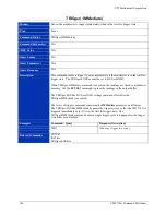
Page 115: ...x MFGTEST 99 Query Parameters N A Query Response 0 1 Description The MFGTEST 99 command enables or disables the ohms current function This can be used to help measure resistance in a circuit with other currents flowing The default setting is enabled Examples Command Query Response Description MFGTEST 99 0 Disables the ohmes current function MFGTEST 99 0 Verifies that the ohms current function is d...

Page 116: ...Trg trigger line STATe Query Parameters trigger line 0 through 7 Query Response 0 1 Description This command enables or disables routing of the voltmeter complete signal to a VXIbus trigger line on the backplane The trigger line parameter specifies which trigger line 0 7 is used The backplane trigger line enable is an additional output to the front panel trigger line that is always present Example...

Page 117: ...t TTLTrig POLarity polarity Command Parameters polarity POS NEG RST Value NEG Query Syntax OUTPut TTLTrig POLarity Query Parameters N A Query Response POS NEG Description Sets the polarity of the voltmeter completed signal to the VXIbus trigger lines Examples Command Query Response Description OUTP POL POS OUTP POL POS Related Commands OUTPut TTLTrg ...

Page 118: ...is on the multimeter samples the input before each measurement and selects the appropriate range Autoranging is automatically disabled if a range is explicitly selected Four different command branches control this one enable disable autorange function RANGe AUTOmatic SENSe CURRent RANGe AUTOmatic SENSe RESistance RANGe AUTOmatic SENSe VOLTage RANGe AUTOmatic The default setting for this function i...

Page 119: ... ac ALL AC Filter settling time1 Low Mid High 1 AC Filter settling time 800 ms 250 ms 60 ms Query Syntax RANGe DELay Query Parameters N A Query Response 1 µs to 2000 s Description This command sets the delay settling time between changing functions or ranges The VM2710A will delay this specified amount of time after a function and or range change before starting to take readings Setting a delay ti...

Page 120: ...fault delay times without having to perform a unit reset Default times are as follows Function Range Time Voltage dc ALL 5 ms Voltage ac ALL AC Filter settling time1 2 4 wire ohms 20 Ω to 200 kΩ 5 ms 2 MΩ 50 ms 20 MΩ 500 ms Current dc ALL 5 ms Current ac ALL AC Filter settling time1 Low Mid High 1 AC Filter settling time 800 ms 250 ms 60 ms Examples Command Query Response Description RANG DEL AUTO...

Page 121: ...ple count and trigger count are not limited Each reading sent to the output buffer consists of 15 bytes characters in real ASCII format 1 234567E 123 LF A Line Feed and an EOF signal follows the last reading instead of a comma The multimeter will remain busy until the readings are removed from the output buffer Any new data sent to the output buffer would overwrite data sent from previous commands...

Page 122: ...ery Parameters MIN MAX specify MIN or MAX available Query Response 1 through 16 777 215 or 1 if MIN specified or 16 777 215 if MAX specified Description The Sample Count command sets the number of readings per trigger If MINimum or MAXimum is specified the command sets or the query returns the value of 1 for MIN and the value of 16 777 215 for MAX The default value is 1 Examples Command Query Resp...

Page 123: ...Ple SOURce Query Parameters N A Query Response IMM TIM Description Sets the pacing source for the sample rate when the SAMPle COUNt is set greater than 1 IMMediate initiates a reading when the multimeter is not busy TIMer specifies to use the TIMer rate setting that is set with the SAMPle TIMer command The default setting is IMMediate Examples Command Query Response Description SAMP SOUR TIM SAMP ...

Page 124: ...ple rate settings The aperture time and sample rate shown assume a fixed range and auto zero off Sample Rate Setting vs Reading Sample Intervals when SAMPle COUNt 2 Aperture Time Samples every reading on every other interval skip 1 sample 2 on every 3rd interval skip 2 sample 2 on every 4th interval skip 3 sample 2 on every 5th interval skip 4 sample 2 2 0 s 2 0 s 4 0 s 6 0s 8 0s 10 0s 1 67 s 1 67...

Page 125: ... returns 100 500 fast mode Query returns 500 RST Value 20 slow mode Query Syntax SENSe BANDwidth DETector Query Parameters N A Query Response 20 100 500 Description This command selects the frequency range or measurement mode for ac voltage The multimeter will automatically set the correct mode slow medium or fast by entering the expected frequency of the input signal Examples Command Query Respon...

Page 126: ...0 1 1 Description This command selects the range for ac current measurements To select a standard measurement range specify the expected value of the input signal s maximum expected current The multimeter then selects the correct range MINimum selects 0 01 A 10 mA range and MAXimum selects 1 A This command overrides any setting by a previous CONFigure command specifying the same function With the ...

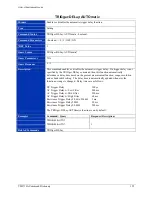
Page 127: ...as shown in the table below Setting to MINimum sets the value to 500 µs setting to MAXimum sets the value to 2 0 seconds The greater the aperture time setting the greater the normal mode rejection and the lower the reading rate Aperture Time Value Entered or returned Frequency 2 0 s 2E 00 50 Hz 1 67 s 1 67E 00 60 Hz 200 ms 2E 01 50 Hz 167 ms 1 67E 01 60 Hz 20 ms 2E 02 50 Hz 16 7 ms 1 67E 02 60 Hz ...

Page 128: ...ption This command selects the range for dc current measurements To select a standard measurement range specify the expected value of the input signal s maximum expected current The multimeter then selects the correct range MINimum selects 0 01 A 10 mA and MAXimum selects 1 A This command overrides any setting by a previous CONFigure command specifying the same function With the new range a new re...

Page 129: ...own in the table below MINimum sets the value to 0 03 PLC MAXimum sets the value to 100 PLC The greater number of PLCs the greater the normal mode rejection and the lower the reading rate Use the CALibration LFRequency command to select the line frequency reference for the multimeter s A D converter Power Line Cycles PLCs Frequency 0 03 PLC 50 Hz 60 Hz 0 1 PLC 50 Hz 60 Hz 1 PLC 50 Hz 60 Hz 10 PLC ...

Page 130: ...ging is on the multimeter samples the input before each measurement and selects the appropriate range Autoranging is automatically disabled if a range is explicitly selected by the CURRent AC RANGe or CURRent DC RANGe command Four different command branches control this one enable disable autorange function RANGe AUTOmatic SENSe CURRent RANGe AUTOmatic SENSe RESistance RANGe AUTOmatic SENSe VOLTag...

Page 131: ...et These four commands perform this exact same function RANGe DELay AUTOmatic SENSe CURRent RANGe DELay AUTOmatic SENSe RESistance RANGe DELay AUTOmatic SENSe VOLTage RANGe DELay AUTOmatic Default times are as follows Function Range Time Voltage dc ALL 5 ms Voltage ac ALL AC Filter settling time1 2 4 wire ohms 20 Ω to 200 kΩ 5 ms 2 MΩ 50 ms 20 MΩ 500 ms Current dc ALL 5 ms Current ac ALL AC Filter...

Page 132: ...Causes the query to report the maximum value 0 0001 Query Response 0 00000001 0 0000001 0 000001 0 00001 0 0001 Description This command sets the resolution for ac measurements MINimum sets the value to 10 nA MAXimum sets the value to 100 µA Note that exponential form may also be used for the resolution value Setting resolution also sets the aperture time and the integration time in power line cyc...

Page 133: ...ses the query to report the maximum value 0 0001 Query Response 0 00000001 0 0000001 0 000001 0 00001 0 0001 Description This command sets the resolution for dc measurements MINimum sets the value to 10 nA MAXimum sets the value to 100 µA Note that exponential form may also be used for the resolution value Setting resolution also sets the aperture time and the integration time in power line cycles...

Page 134: ...function type FRESistance RESistance VOLTage AC VOLTage DC RST Value VOLTage DC Query Syntax SENSe FUNCtion Query Parameters N A Query Response FRES RES VOLT AC VOLT Description This command selects the measurement function of the multimeter The default function is dc voltage Examples Command Query Response Description FUNC RES Selects the 2 wire ohms function FUNC RES Related Commands N A ...

Page 135: ... the nearest aperture time as shown in the table below Setting to MINimum sets the value to 500 µs setting to MAXimum sets the value to 2 0 seconds The greater the aperture time setting the greater the normal mode rejection and the lower the reading rate Aperture Time Value Entered or returned Frequency 2 0 s 2E 00 50 Hz 1 67 s 1 67E 00 60 Hz 200 ms 2E 01 50 Hz 167 ms 1 67E 01 60 Hz 20 ms 2E 02 50...

Page 136: ...ters boolean 0 1 OFF ON RST Value 0 Query Syntax SENSe RESistance NEGative Query Parameters N A Query Response 0 1 Description This command when active prevents negative resistance values from being reported by the VM2710A The reset state is 0 which will report negative values Examples Command Query Response Description RES NEG 1 Enables filtering of negative resistance values they will not be rep...

Page 137: ...hown in the table below MINimum sets the value to 0 03 PLC MAXimum sets the value to 100 PLC The greater number of PLCs the greater the normal mode rejection and the lower the reading rate Use the CALibration LFRequency command to select the line frequency reference for the multimeter s A D converter Power Line Cycles PLCs Frequency 0 03 PLC 50 Hz 60 Hz 0 1 PLC 50 Hz 60 Hz 1 PLC 50 Hz 60 Hz 10 PLC...

Page 138: ... command selects the range for resistance measurements To select a standard range select the expected value as the input signal s maximum expected resistance The multimeter then automatically selects the correct range Also MINimum 0 Ω or MAXimum 20 MΩ may be specified The Resistance Range command overrides the range setting from a previous CONFigure command specifying the resistance range With the...

Page 139: ...rements When autoranging is on the multimeter samples the input before each measurement and selects the appropriate range Autoranging is automatically disabled if a range is explicitly selected by the RESistance RANGe command Four different command branches control this one enable disable autorange function RANGe AUTOmatic SENSe CURRent RANGe AUTOmatic SENSe RESistance RANGe AUTOmatic SENSe VOLTag...

Page 140: ...a unit reset These four commands perform this exact same function RANGe DELay AUTOmatic SENSe CURRent RANGe DELay AUTOmatic SENSe RESistance RANGe DELay AUTOmatic SENSe VOLTage RANGe DELay AUTOmatic Default times are as follows Function Range Time Voltage dc ALL 5 ms Voltage ac ALL AC Filter settling time1 2 4 wire ohms 20 Ω to 200 kΩ 5 ms 2 MΩ 50 ms 20 MΩ 500 ms Current dc ALL 5 ms Current ac ALL...

Page 141: ...t the minimum value 0 0001 Ω MAX Causes the query to report the maximum value 1000 Ω Query Response 0 0001 0 001 0 01 0 1 1 10 100 1000 Description This command sets the resolution for resistance measurements MINimum sets the value to 100 µΩ MAXimum sets the value to 1 kΩ Setting resolution also sets the aperture time and the integration time in power line cycles This command can override the prev...

Page 142: ...V Description This command selects the range for ac voltage measurements To select a standard measurement range specify the expected value of the input signal s maximum expected voltage The multimeter then selects the correct range MINimum selects 0 0 V and MAXimum selects 300 0 V This command overrides any setting by a previous CONFigure command specifying the same function With the new range a n...

Page 143: ...hown in the table below Setting to MINimum sets the value to 500 µs setting to MAXimum sets the value to 2 0 seconds The greater the aperture time setting the greater the normal mode rejection and the lower the reading rate Aperture Time Value Entered or returned Frequency 2 0 s 2E 00 50 Hz 1 67 s 1 67E 00 60 Hz 200 ms 2E 01 50 Hz 167 ms 1 67E 01 60 Hz 20 ms 2E 02 50 Hz 16 7 ms 1 67E 02 60 Hz 2 0 ...

Page 144: ...0 0 V Description This command selects the range for dc voltage measurements To select a standard measurement range specify the expected value of the input signal s maximum expected voltage The multimeter then selects the correct range MINimum selects 0 0 V and MAXimum selects 300 0 V This command overrides any setting by a previous CONFigure command specifying the same function With the new range...

Page 145: ...own in the table below MINimum sets the value to 0 03 PLC MAXimum sets the value to 100 PLC The greater number of PLCs the greater the normal mode rejection and the lower the reading rate Use the CALibration LFRequency command to select the line frequency reference for the multimeter s A D converter Power Line Cycles PLCs Frequency 0 03 PLC 50 Hz 60 Hz 0 1 PLC 50 Hz 60 Hz 1 PLC 50 Hz 60 Hz 10 PLC ...

Page 146: ...on the multimeter samples the input before each measurement and selects the appropriate range Autoranging is automatically disabled if a range is explicitly selected by the VOLTage AC RANGe or VOLTage DC RANGe command Four different command branches control this one enable disable autorange function RANGe AUTOmatic SENSe CURRent RANGe AUTOmatic SENSe RESistance RANGe AUTOmatic SENSe VOLTage RANGe ...

Page 147: ...et These four commands perform this exact same function RANGe DELay AUTOmatic SENSe CURRent RANGe DELay AUTOmatic SENSe RESistance RANGe DELay AUTOmatic SENSe VOLTage RANGe DELay AUTOmatic Default times are as follows Function Range Time Voltage dc ALL 5 ms Voltage ac ALL AC Filter settling time1 2 4 wire ohms 20 Ω to 200 kΩ 5 ms 2 MΩ 50 ms 20 MΩ 500 ms Current dc ALL 5 ms Current ac ALL AC Filter...

Page 148: ...1 MAX Causes the query to report the maximum value 0 01 Query Response 0 0000001 0 000001 0 00001 0 0001 0 001 0 01 Description This command sets the resolution for voltage measurements MINimum sets the value to 100 nV MAXimum sets the value to 10 mV Note that exponential form may also be used for the resolution value Setting resolution also sets the aperture time and the integration time in power...

Page 149: ...AX Causes the query to report the maximum value 0 01 Query Response 0 0000001 0 000001 0 00001 0 0001 0 001 0 01 Description This command sets the resolution for voltage measurements MINimum sets the value to 100 nV MAXimum sets the value to 10 mV Note that exponential form may also be used for the resolution value Setting resolution also sets the aperture time and the integration time in power li...

Page 150: ...yntax TEST Query Parameters N A Query Response number Description The TEST command performs an internal unit self test Disconnect all input signals before running the self test or there may be errors A zero is returned when the test has completed with no errors Examples Command Query Response Description TEST Performs an internal self test and reports the results Related Commands TST ...

Page 151: ...rogram the module and query the module s settings When fast response time is important measurements can be retrieved using register access The two methods are exclusive only one can be used at a time Setting TRACe FEED to OFF is the way to use word serial data transfers this is the unit default Setting TRACe FEED to REGister is the way to use register access Note that in register access mode the M...

Page 152: ... the trigger buffer and corrects for a trigger too fast type of error This mode is only used with the front panel external trigger With the Trigger Buffer on if a trigger occurs during a reading the trigger is stored and no error is generated After the reading is complete the stored trigger satisfies the EXT event if the multimeter is programmed as such However a second trigger occurring during a ...

Page 153: ...When setting the trigger count the memory 64 k or 256 k readings must be taken into consideration for the trigger count multiplied by the sample count SAMPle COUNt must be less than or equal to the memory capability When set to 0 countinuous the voltmeter returns to the waiting for trigger state after each trigger This is particularly useful when using the register interface and an extrenal trigge...

Page 154: ...mmand sets the delay period between receipt of the trigger and the start of the measurement If a trigger period is specified by this command then the TRIGger DELay AUTOmatic function is automatically turned off The delay period value set by this command remains set until a new value is entered or the multimeter is reset The period values are accurate down to 150 µs If a value below 150 µs is speci...

Page 155: ...nd then this function automatically determines a delay time based on the present measurement function range resolution and ac bandwidth setting The delay time is automatically updated whenever the function or range is changed Delay times are as follows DC Trigger Delay 100 µs AC Trigger Delay w Low Filter 500 ms AC Trigger Delay w Mid Filter 250 ms AC Trigger Delay w High Filter 60 ms Resistance T...

Page 156: ...command is executed the readings are stored in multimeter memory Use the FETCh command to place the readings in the output buffer The TRIGger SOURce BUS or HOLD settings remain in effect after the TRIGger IMMediate is executed The levels of trigger commands containing the IMMediate parameter are different The TRIGger SOURce IMMediate bypasses the trigger system so that the VM2710A is triggered imm...

Page 157: ... the positive or negative edge RST Value NEG Query Syntax TRIGger SLOPe Query Parameters N A Query Response POS NEG Description This command determines whether the rising or falling edge of the front panel signal will trigger the multimeter Examples Command Query Response Description TRIG SLOP POS Sets the multimeter to trigger on the rising edge of the front panel signal TRIG SLOP POS Related Com...

Page 158: ...ger setting EXTernal The VM2710A s front panel connector If EXTernal is selected then the trigger comes from the front panel connector input HOLD Suspend triggering only the TRIGger IMMediate command will generate a trigger When HOLD is selected ABORt returns the VM2710A to idle state The READ command cannot be used with this trigger setting IMMediate The trigger system is always true A trigger wi...

Page 159: ...mand Syntax N A Command Parameters N A RST Value N A Query Syntax STATus OPERation CONDition Query Parameters N A Query Response 0 32 Description Reports the bits set in the Operation Status Register s condition register Returns a decimal number of 0 no bits set or 32 bit 5 set Examples Command Query Response Description STAT OPER COND 0 Related Commands STATus OPERation ENABle STATus OPERation EV...

Page 160: ...meters N A Query Response NRf Numeric ASCII value from 0 to 32767 Description This command enables bits in the Operation Status Register s enable register to report to the summary bit sets Status Bytes register bit 7 to true The query reports the bits enabled in the Operation Status Register s enable register then clears the register contents and enters the value into the computer Examples Command...

Page 161: ...yntax N A Command Parameters N A RST Value N A Query Syntax STATus OPERation EVENt Query Parameters N A Query Response 0 Description Queries the bits set in the Operation Status Register s event register This command clears all bits in the event register Examples Command Query Response Description STAT OPER 0 Related Commands STATus OPERation CONDition STATus OPERation ENABle ...

Page 162: ...meters N A RST Value N A Query Syntax N A Query Parameters N A Query Response N A Description The Status Preset command presets the Status Registers The Operational Status Enable Register is set to 0 and the Questionable Status Enable Register is set to 0 This command is provided for SCPI compliance only Examples Command Query Response Description STAT PRES Related Commands N A ...

Page 163: ... N A Command Parameters N A RST Value N A Query Syntax STATus QUEStionable CONDition Query Parameters N A Query Response 0 Description The Questionable Status Condition Register query is provided for SCPI compliance only The VM2710A does not alter any bits in this register and a query always reports a 0 Examples Command Query Response Description STAT QUES COND 0 Related Commands N A ...

Page 164: ...le Query Parameters N A Query Response NRf Numeric ASCII value from 0 to 32767 Description The command sets the bits in the Questionable Data Signal Register s enable register to be reported to the summary bit sets Status Byte Register bit 3 to true The Status Questionable Enable query reports the contents of the Questionable Data Signal Register s enable register then clears the register contents...

Page 165: ...RST Value N A Query Syntax STATus QUEStionable EVENt Query Parameters N A Query Response Decimal number Description The query reports the bits set in the Questionable Data Signal register s event register This command reads the event register and then clears all bits in the event register and enters the value into the computer Examples Command Query Response Description STAT QUES 0 Related Command...

Page 166: ...e error messages from the error queue The error queue will maintain two error messages If additional errors occur the queue will overflow and the subsequent error messages will be lost In the case of an overflow an overflow message will replace the second error message See the SCPI standard Volume 2 Command Reference for details on errors and reporting them A list of error codes is provided in the...

Page 167: ...21 Settings conflict Can t change input source while running 221 Settings conflict Can t change math setting while running 221 Settings conflict Can t perform selftest while running 221 Settings conflict DOWNLOAD can only be used by the top module 221 Settings conflict Can t change trigger source while running 221 Settings conflict Can t change sample count while running 221 Settings conflict Can ...

Page 168: ...or Unrecognized calculate function 310 System error Unrecognized overflow type 310 System error Nonvol has wrong data using defaults 310 System error Unrecognized internal trigger source 310 System error Unrecognized internal trigger sourc 310 System error Unrecognized internal sample count 310 System error Unrecognized sample source 310 System error Unrecognized sample period 310 System error Unr...

Page 169: ...ired SCPI command Command Syntax N A Command Parameters N A RST Value N A Query Syntax SYSTem VERSion Query Parameters N A Query Response Numeric ASCII value Description The System Version query reports version of the SCPI standard with which the VM2710A complies Examples Command Query Response Description SYST VERS 1994 0 Related Commands N A ...

Page 170: ...ate LIMit LOWer TTLTrg 47 71 CALCulate LIMit UPPer 47 72 CALCulate LIMit UPPer TTLTrg 47 73 CALCulate NORead 47 75 CALCulate NULL OFFSet 47 74 CALCulate STATe 47 76 CALibration CONVert GAIN CURRent AC 39 47 78 CALibration CONVert GAIN CURRent DC 39 47 79 CALibration CONVert GAIN FRESistance 39 47 80 CALibration CONVert GAIN RESistance 39 47 81 CALibration CONVert GAIN VOLTage AC 39 47 82 CALibrati...

Page 171: ... MFGTEST 33 44 MFGTEST 34 44 MFGTEST 35 44 MFGTEST 4 42 MFGTEST 5 42 MFGTEST 6 43 MFGTEST 7 43 MFGTEST 8 43 N noise rejection 14 non volatile memory 14 O OPC 46 OUTPut TTLTrg 48 122 OUTPut TTLTrg POLarity 48 123 overheating 10 P parameter 30 31 power 25 26 45 55 power cord 10 probes 10 programming language 29 pseudo register access 31 R RANGe AUTOmatic 48 124 RANGe DELay 48 125 RANGe DELay AUTOmat...

Page 172: ...nstruments Corporation 172 VM2710A Index TRIGger SOURce 49 164 TRIGger IMMediate 49 162 TST 46 V ventilation 10 VMIP 13 14 26 VXIbus 13 14 25 29 33 W WAI 46 wet or damp conditions 10 word serial protocol 14 ...

Reviews: