27
When soldering ICs, try to keep the IC from getting too hot. As a rule of thumb don’t keep your
iron on any leg longer than two seconds, and make sure the chip stays cool enough to touch.
Solder one leg at time and let the chip cool off before proceeding to the next leg.
ICs have a specific orientation. If you install them wrong, your pedal will not work and you could
damage or destroy the IC. Each IC has a dot or a divot at one corner or end. These features
have a corresponding graphic in “Figure 4: Component Values and Locations” on page 11,
and/or on the PCB, to show you how to orient the IC.
a. Microcontroller, ATmega328-PU (U1): This IC is the “brain” of the Quaverato. We pre-
programmed this chip with software which tells the pedal how to operate. This software is
open-source and published under the creative commons license. To learn how to modify the
software to make your Quaverato behave differently, please visit our
GitHub page
. You can
use the popular development environment Arduino to edit and modify the code.
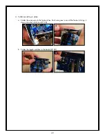
We will not actually be soldering the microcontroller to the PCB itself; instead we will solder
an IC socket to the board and install the microcontroller into the socket.
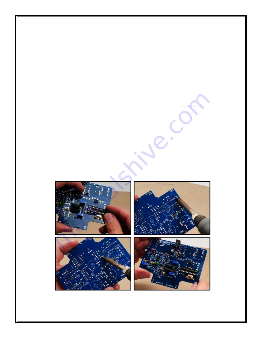
i. Install the 28-pin socket (part #HE-25-28) in the U1 location (78). Please note the divot
at one end of the socket. This end should align with the dot on the PCB graphic.
ii. Hold down the socket with one finger while you flip the board over. Tack down one pin
with a tiny bit of solder (79).
iii. Now solder the rest of the pins (80). Don’t forget to go back to the original “tacked
down” pin to finish soldering that correctly (81).
78
79
80
81


