Information text upper line programming unit:
- RESOLVERA1 ' Resolver feedback axis 1.
- FINE = XXXX ' Actual position of the fine resolver in resolver
increments.
- SYNCPAR = YYYY ' Active resolver offset in robot increments for fine or
coarse resolver obtained from the parameter memory.
- COUNTER=XXXXX ' The actual value of the counter in whole resolver turns.
- CPAR=YYYYY ' Actual value of turn counter obtained from the
parameter memory. The value of the counter in the
calibration position is required for calculation of present
position at power-up.
In the case with coarse resolver:
- COARSE=XXXXX ' Actual position of the coarse resolver in resolver
increments.
5.3.3
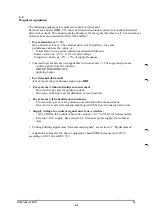
Handling of calibration parameters
1. Introduction:
The control system can be in the MOTOR ON mode. The joystick is however blocked in
the menu when UPDATE can be selected to prevent motor and resolver axes changing
positions in connection with this function:
2. The function UPDATE:
- Before an axis number is selected, the associated motor and resolver axis must be in
the correct position for the operation intended. In the case when only the counter is to
be updated is it sufficient to position the robot according to the calibration scales on
the robot. Note that all axes must be in the right position.
- While in the menu in which UPDATE can be executed, the actual position of the
resolver (FINE = XXXX or COARSE = YYYY) is presented the form of a mean value of
all samples (2 times/sec). Before selecting UPDATE , it is advised to wait for approx.
1.5 s after having run the robot.
- When UPDATE is pressed, the actual mean value of the resolver position is
transferred to the parameter memory.
3. The function MAN DEF:
a) Method A:
- An axis selected previously can be run to the correct position after the selection of
MAN DEF.
- The actual position of the resolver (FINE = XXXX or COARSE = YYYY) is presented
without the calculation of mean value.
- After adjustment, the value presented can be read in and is then transmitted to the
parameter memory.
b) Method B:
- Manual reading-in of commutation and resolver offset to the parameter memory
with values in accordance with the robot identification documentation.
- The value of the counter can NOT be defined manually.
4. Auxiliary function:
- NEXT ' Selection of the next axis in consecutive order.
- ENTER = without entry of data
' No updating of the parameter memory.
- BREAK ' Return to proceeding menu.
- ACTIVE ' Conclusion.
5. Conclusion:
When the check or change is complete, the concluding action is to press ACTIVE in the
proceeding menu. The changed parameters are actuated after the concluding
initialization of the control system. The control system is then in the MOTOR OFF
mode and unsynchronized in case that NOT all axes has absolute measurement.
INSTALLATION S3
5:62
Summary of Contents for IRB 2000
Page 8: ...Description 1KB 2000 ...
Page 10: ...Description 1KB 2000 ...
Page 12: ...Description 1KB 2000 6 ...
Page 20: ...Description 1KB 2000 14 ...
Page 32: ...Description 1KB 2000 26 ...
Page 40: ...5 3 2 Dimensional drawings Description 34 1KB 2000 ...
Page 41: ..._200 _D D_ Description 35 1KB 2000 ...
Page 44: ...Description 1KB 2000 38 ...
Page 64: ...Description 1KB 2000 58 ...
Page 77: ...Safety 1KB 2000 IBB 3000 12 1KB 3200 1KB 6000 ...
Page 80: ...Installation H B 2000 ...
Page 82: ...Installation 1KB 2000 ...
Page 91: ...Installation 1KB 2000 12 ...
Page 95: ...Installation 1KB 2000 16 ...
Page 110: ...INSTALLATION S3 0 4 ...
Page 112: ...INSTALLATION S3 1 2 ...
Page 160: ...INSTALLATION 3 46 ...
Page 234: ...INSTALLATION 5 70 ...
Page 262: ...INSTALLATION S3 7 6 ...


