MC97F6108A User’s manual
9. Watchdog Timer (WDT)
81
9.4
Register description
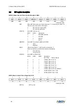
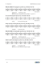
WDTR (Watchdog Timer Register: Write Case): 8EH
7
6
5
4
3
2
1
0
WDTR7
WDTR 6
WDTR 5
WDTR 4
WDTR 3
WDTR 2
WDTR 1
WDTR 0
W
W
W
W
W
W
W
W
Initial value: FFH
WDTR[7:0]
Set a period
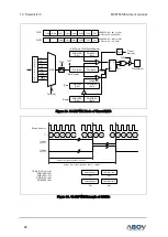
WDT Interrupt Interval=(BIT Interrupt Interval) x(WDTDR Value+1)
NOTE:
Do not write
“0” in the WDTDR register. To guarantee proper operation, the data
should be greater than 01H.
WDTCR (Watchdog Timer Counter Register: Read Case): 8EH
7
6
5
4
3
2
1
0
WDTCR 7
WDTCR 6
WDTCR 5
WDTCR 4
WDTCR3
WDTCR 2
WDTCR 1
WDTCR 0
R
R
R
R
R
R
R
R
Initial value: 00H
WDTCNT[7:0]
WDT Counter
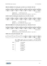
WDTMR (Watchdog Timer Mode Register): 8DH
7
6
5
4
3
2
1
0
WDTEN
WDTRSON
WDTCL
WDTCK
–
–
–
WDTIFR
R/W
R/W
R/W
R/W
–
–
–
R/W
Initial value: 00H
WDTEN
Control WDT Operation
0
Disable
1
Enable
WDTRSON
Control WDT RESET Operation
0
Free Running 8-bit timer
1
Watch Dog Timer RESET ON
WDTCL
Clear WDT Counter
0
Free Run
1
Clear WDT Counter (auto clear after 1 Cycle)
WDTCK
Control WDT Clock Selection Bit
0
BIT overflow for WDT clock
1
BIT Clock Source for WDT clock
WDTIFR
When WDT Interrupt occurs, this bit becomes
‘1’. For clearing bit, write ‘0’
to this bit or auto clear by INT_ACK signal.
0
WDT Interrupt no generation
1
WDT Interrupt generation


