7
SETUP
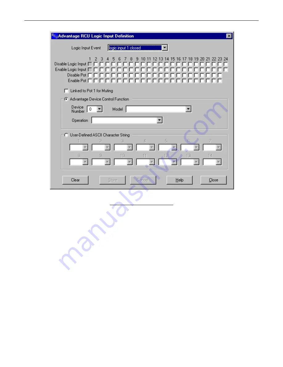
LOGIC INPUT DEFINITION SCREEN
Up to 24 contact-closures may be connected to the Logic Inputs port of the RCU. Contact-closures may be switches, relays, or logic
outputs from other devices. Each logic input may be programmed to perform a specific control function for a specific product. This
programming process is performed using the “Advantage Device Control Function” section of the Logic Input Definition Screen. Each
product that is linked to the RCU must have a unique device number. When creating a logic input definition, you must specify the device
number of the product which that logic input will be controlling. You must also specify the model of the product (VRAM, MSP22e, etc.).
Once you have specified the model, a list of available operations appears in the “Operation” list box. The list of operations changes
depending upon which model is selected. When a definition has been established for a particular logic input, an icon and device number
will appear above the ‘LED’ indicator on the Main Screen. The icon and device number indicate which device the logic input is
programmed to control. When the mouse pointer is positioned over the LED indicator, a pop-up ‘hint’ appears which provides a detailed
description of the function which the logic input is programmed to perform. In addition to specifying which actions occur when a contact
closes, you also may specify which actions occur when a contact opens. Normally, each of the 24 logic inputs acts independently of the
others. Using the Configuration Options Screen, the six highest logic inputs (19 through 24) may be programmed to operate in ‘binary’
mode. When in binary mode, a logic input definition may be created for each of the 64 possible binary on/off combinations of logic inputs
19 through 24. Logic inputs may also be programmed to enable/disable other logic inputs or pots, or to transmit a user-defined ASCII
character string (this programming does NOT require a device number or product model be specified). Individual checkboxes are provided
for disabling or enabling each of the other logic inputs, as well as for disabling or enabling each of the 23 pots. The Logic Input Definition
Screen prevents you from disabling or enabling the logic input which is currently being defined. You should be careful not to create a
situation where one or more pots or logic inputs have been disabled with no way of becoming re-enabled again (if you find yourself in such
a situation, a quick way of re-enabling all pots and logic inputs can be found on the Configuration Options Screen). When programming a
logic input to transmit a user-defined ASCII character string, you may define a string of up to 14 characters. This string may consist of any
combination of ASCII characters except for the NUL character (whose decimal value is zero). ASCII character strings may be used to write
advanced product/function commands which are not available from the ‘Options’ list box (see Computer Control Manual for the product to
be controlled). Single ASCII characters may also be used to emulate remote control buttons, which are then programmable on an
individual product basis, using this same BiampWin software (see RS-232 Control on pg. 10).


