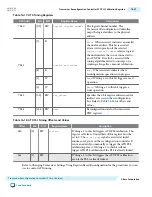
PHY Addr
Bits R/W
Register Name
Description
[1]
W
Read
. Writing a 1 to this bit triggers a read
operation. This bit is self clearing.
[0]
W
Write
. Writing a 1 to this bit triggers a write
operation. This bit is self clearing.
7’h3B
[15:0
]
RW
streamer offset
When the
MIF Mode
= 2’b00, the offset register
specifies a an internal MIF Streamer register.
This register cannot be set to a value greater
than 0x2 when
control and status
register
is set to
MIF mode
. You must ensure that
appropriate values are set for this register,
when you switch between
MIF mode
and
Direct Write mode
. Refer to
Table 16-25
for
definitions of these registers. When
MIF Mode
=
2’b01, offset register specifies register in the
transceiver.
7’h3C
[31:0
]
RW
data
When the
MIF Mode
= 2’b00, the data register
stores read or write data for indirect access to
the location specified in the offset register.
When
MIF Mode
= 2’b01, data holds an update
for transceiver to be dynamically reconfigured.
Note: All undefined register bits are reserved.
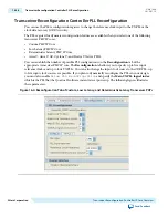
Table 16-25: Streamer Module Internal MIF Register Offsets
Offset
Bits
R/W
Register Name
Description
0x0
[31:0] RW
MIF base address
Specifies the MIF base address.
0x1
[2]
RW
Clear error status
Writing a 1 to this bit clears any error
currently recorded in an indirect register.
This register self clears.
Any error detected in the error registers
prevents MIF streaming. If an error occurs,
you must clear the error register before
restarting the Streamer.
[1]
RW
MIF address mode
When set to 0, the streamer uses byte
addresses. When set to 1, the streamer uses
word addresses (16 bits).
[0]
RW
Start MIF stream
Writing a 1 to this register, triggers a MIF
streaming operation. This register self
clears.
UG-01080
2015.01.19
Transceiver Reconfiguration Controller Streamer Module Registers
16-35
Transceiver Reconfiguration Controller IP Core Overview
Altera Corporation
Send Feedback


