46
Atmel AVR2052
8200M-AVR-11/11
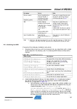
b. For REB-CBB:
a. Attach the radio extender board to the REB-CBB and connect
a power cable to the PWR port on the REB-CBB.
b. Connect the RS-232 interface cable to the USARTD0 port on
the REB-CBB and to the COM1 port on the PC.
Table 11-5.
Host UART and MCU pin connections.
UART pin on host device
ATxmega256A3/D3 MCU pin
RXD
PD2
TXD
PD3
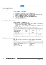
2. Install and run the Bootloader PC tool from the command line or use the GUI.
Specify the target image file in
.srec
format and the COM port, and launch the
firmware upload.
3. Reset the board using the reset button, if requested.
4. The Bootloader PC tool indicates the programming progress. Once an upload is
successfully completed, the board should restart automatically. If an upload fails,
the Bootloader PC tool should indicate the reason. In rare cases, the booting
process can fail due to communication errors between the board and the PC. If
this happens, attempt booting again or try using the conventional serial port
instead of USB. If booting fails, the program recently written to the board will be
corrupted, but the board can be reprogrammed, as the embedded bootloader
remains intact.
See
for additional details about the Serial Bootloader package.
WARNING
Using JTAG to program the microcontroller will erase the embedded
bootloader, making the loading of application images with Serial
Bootloader impossible until the embedded bootloader firmware is
reprogrammed to the device.
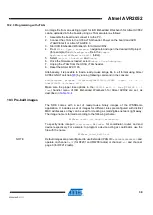
11.2.4 Programming with JTAG
the description of how the images can be programmed to the boards using JTAG.
•
For STK600:
the JTAGICE device must be connected to a particular JTAG
connector on the STK600 board. This connector is not marked with any label, and
is situated next to the connector marked as JTAG (in the blue background area),
but closer to the ATxmega expansion board.
Note that the Atmel ATxmega256D3 devices support only PDI programming. The
PDI connector can be found next to the JTAG connector on the STK600 board. A
special XMEGA PDI adapter must be used with JTAG for programming
ATxmega256D3 devices.
•
For REB-CBB
: connect the JTAGICE device to the DBG port on a REB-CBB
board.
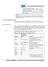
Make sure that the board and ATxmega socket card are powered on (refer to Section
for the description of additional steps required for that) and the right options set
in the
Fuses
tab (see
) before uploading the image through JTAG. Don’t
forget to select the correct device (the Atmel ATxmega256A3 or ATxmega256D3) in
the Device and Signature Bytes field on the Main tab of the programming dialogue.
After programming the image, reset the board.


