Commissioning
EL3773
91
Version: 2.5
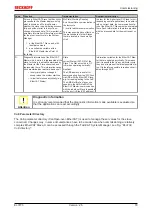
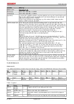
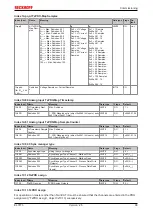
Variable
Meaning
Status word
Overrange
Value after calibration > 0x7FFF
Underrange
Value after calibration < 0x8000
SyncError
- In DC mode: indicates whether a synchronization error occurred in the expired cycle.
This means a SYNC signal was triggered in the terminal, although no new process
data were available (0=OK, 1=NOK).
- Error in the synchronous oversampling, e.g. the number of ADC values and the
number of PDO values do not match.
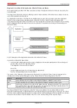
StartTimeNextLatch In the 64-bit-wide process data
StartTimeNextLatch,
as was also the case with
previous EL37xx terminals, the time is specified in each process data cycle when the
next
SYNC1 pulse and thus the next block of sample values begins, referenced to the
currently transmitted block
.
StartTimeNextLatch thus changes in each cycle by the
amount of that task cycle time with which this terminal is operated. This time
specification is based on the terminal’s local Distributed Clocks time.
By means of this time specification a concrete time can to be assigned to each
individual sample with the known oversampling factor.
Example:
With a cycle time of 1 ms (= 1,000,000 ns) and an oversampling factor of 10 in the
regarded cycle, the EL3773 supplies a StartTimeNextLatch = 7,777,216
dec
and 6 x 10
measured values at 16 bits each as process data (3 x U, 3 x I).
The time of measurement of the 5
th
supplied sample is now to be determined, i.e. the
Distributed Clocks time at which the 5
th
sample was determined.
The currently supplied set of 10 samples was started at the time 7,777,216 –
1,000,000 (cycle time) = 6,777,216 ns. The time interval between the samples is
1,000,000 / 10 = 100,000 ns. Hence, the 5
th
sample was determined at the time
6,777,216 + ((5 - 1) * 100,000) = 7,177,216 ns.
Cycle Count
The cycle counter is incremented by one unit with each process data cycle. The
CycleCounter enables the higher-level controller to check whether a data record has
possibly been omitted or transmitted twice. In that case the DC shift time of the
terminal usually has to be adapted.
DcOutputShift,
DcInputShift
In these static variables the System Manager announces the shift time to which this
terminal has been set. The value is set once on activating/calculating the configuration
and also depends on the customer-specific settings in the extended slave settings.
It can be linked to offset calculations in the PLC.
Control/status word
Status word
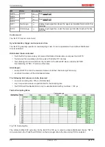
The status word (SW) is located in the input process image, and is transmitted from terminal to the controller.
Bit
SW.15
SW.14
SW.13
SW.12
SW.11
SW.10
SW.9
SW.8
Name
TxPDO
Toggle
TxPDO
State
Sync
error
-
-
-
-
-
Bit
SW.7
SW.6
SW.5
SW.4
SW.3
SW.2
SW.1
SW.0
Name
-
ERROR
Limit 2
Limit 1
Overrange Underrange
Table 1: Legend
Bit
Name
Description
SW.15
TxPDO
Toggle
1
bin
Toggles with each new analog process value
SW.14
TxPDO State
1
bin
TRUE in the case of an internal error
SW.13*
Sync error
1
bin
TRUE (DC mode): a synchronization error occurred in the expired
cycle.
SW.6
ERROR
1
bin
General error bit, is also set together with overrange and underrange
Summary of Contents for EL3773
Page 1: ...Documentation EL3773 Power Monitoring Oversampling Terminal 2 5 2018 03 13 Version Date...
Page 2: ......
Page 6: ...Table of contents EL3773 6 Version 2 5...
Page 39: ...Mounting and wiring EL3773 39 Version 2 5 Fig 29 Other installation positions...
Page 41: ...Mounting and wiring EL3773 41 Version 2 5 Fig 31 Block diagram...
Page 47: ...Commissioning EL3773 47 Version 2 5 Fig 38 Incorrect driver settings for the Ethernet port...
Page 147: ...Commissioning EL3773 147 Version 2 5 Fig 168 Confirming program start...

