X2 Control communication with BFI-E3 by Modbus TCP
SER0020_V1.0.0 2020-11
24 (31)
Nor
m
a
l.d
o
tm
,
2
0
2
0
-07
-01
40
-
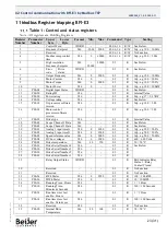
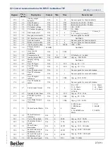
Speed Reference
U16
0
P-01
03
R
3000=50 Hz
41
-
Reserved
-
-
-
03
R
No Function
42
-
Digital Pot / Keypad
Reference
U16
0
P-01
03
R
3000=50 Hz
43
P00-07
Output Voltage
U16
0
-
03
R
100=100 VAC RMS
44
-
Parameter Access
Index
U16
1
60
03
R
See Below
45
-
Parameter Access
Value
S16
-
-
03
R
See Below
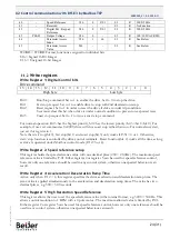
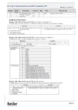
WORD = WORD Format, functions assigned to individual bits
S16 = Signed 16 Bit Integer
U16 = Unsigned 16-bit Integer
Write registers
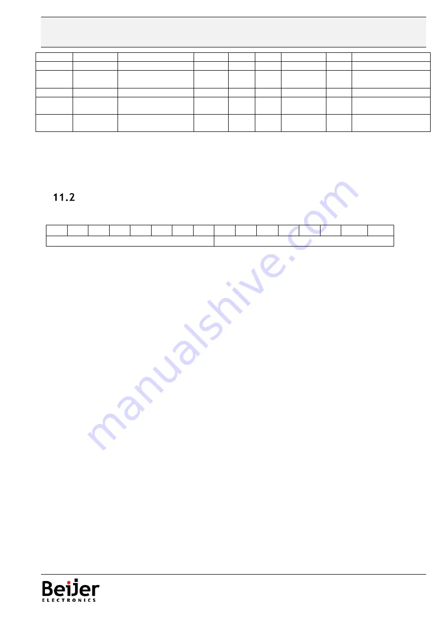
Write Register 1: Digital Control bits
Drive command
15
14
13
12
11
10
9
8
7
6
5
4
3
2
1
0
High byte
Low byte
Bit 0:
Run/Stop command: Set to 1 to enable the drive. Set to 0 to stop the drive.
Bit 1:
Fast stop request. Set to 1 to enable drive to stop with 2nd deceleration ramp.
Bit 2:
Reset request. Set to 1 in order to reset the drive if drive is under trip condition.
User must clear this bit when drive is under normal condition to prevent un-expected reset.
Bit 3:
Coast stop request. Set to 1 to issue a coast stop command.
For normal operation, Bit 3 has the highest priority, bit 0 has the lowest priority (bit 3>bit 1>bit 0). For
example, if user set command as 0x0009, drive will do a coast stop rather than run. For normal run/start,
just set this register to 1.
Note that stat/stop(bit 0), fast stop(bit 1) and coast stop(bit 3) only works if P-31= 0 or 1. Otherwise,
start/stop function is controlled by drive control terminals. Reset function(bit 2) works all the time as long
as drive is operated under Modbus control mode (P-12=3 or 4).
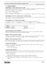
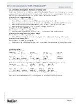
Write Register 2: Speed reference setup
This register holds the speed reference value with one decimal place (200 = 20.0Hz). The maximum speed
reference value is limited by P-01. Either register 2 or register 5 can be used for speed reference control,
however only one reference should be used in any control system, otherwise unexpected behaviour can
result.
Write Register 4: Acceleration /Deceleration Ramp Time
Active only when P-12 = 4, this register specifies the drive acceleration and deceleration ramp time. The
same value is applied simultaneously to the acceleration and deceleration ramp times. The value has two
decimal places, e.g. 500 = 5.00 seconds.
Write Register 5: High Resolution Speed Reference
This register allows the user to set the speed reference value in the internal format, e.g. 3000 = 50.0Hz. This
allows control resolution to 1 RPM with a 2-pole motor . The maximum allowed value is limited by P-01.
Either register 2 or register 5 can be used for speed reference control, however only one reference should be
used in any control system, otherwise unexpected behaviour can result.

