background image

 
X2 Control communication with BFI-E3 by Modbus TCP 


SER0020_V1.0.0  2020-11


26 (31)


Nor

m

a

l.d

o

tm

2

0

2

0

-07

-01


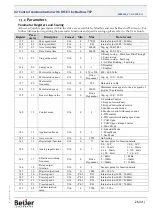
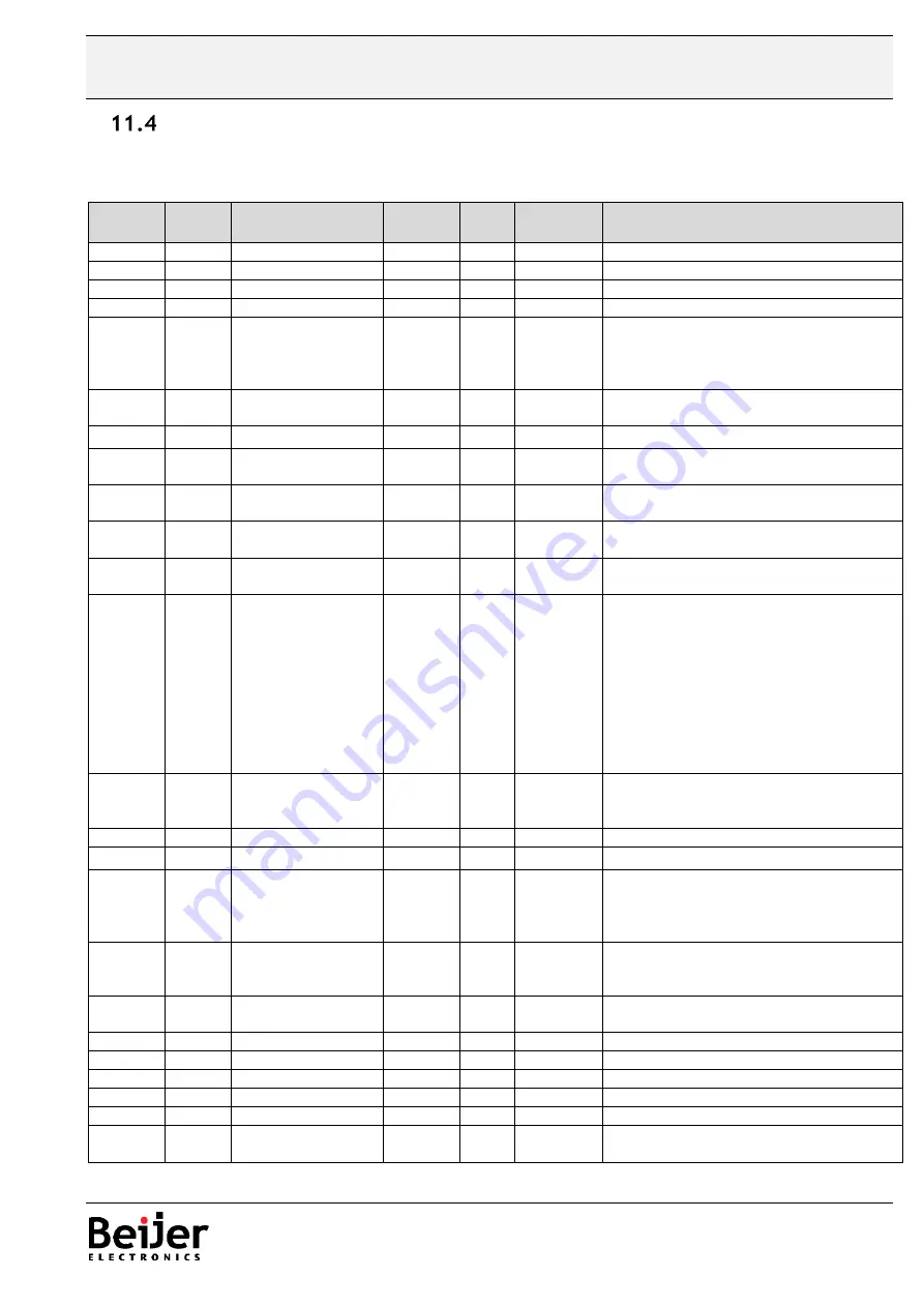
Parameters 

Parameter Registers and Scaling 

All user adjustable parameters within the drive are accessible by Modbus and can be Read or Written to. For 

further information regarding the parameter functions and specific settings, please refer to the User Guide. 

Register 

Para-

meter 

Description 

Format 

Min 

Max 

Data format 

129 

01 

Max speed limit 

U16 

5*P-09 

Internal value (3000 = 50.0Hz) 

130 

02 

Min speed limit 

U16 

P-01 

Internal value (3000 = 50.0Hz) 

131 

03 

Accel ramp time 

U16 

60000 

2dp, e.g. 300=3.00s 

132 

04 

Decel ramp time 

U16 

60000 

2dp, e.g. 300=3.00s 

133 

05 

Stop mode select 

U16 

0: Ramp to stop + Main Loss Ride Through 
1: Coast to stop 
2: Ramp to stop + Fast Stop 
3 : AC Flux B Fast Stop  

134 

06 

Energy save 

U16 

0: Disabled 
1: Enabled 

135 

07 

Motor rated voltage 

U16 

250 or 500 

400 = 400 Volts 

136 

08 

Motor rated current 

U16 

Drive 

Dependent 

1dp, e.g. 100 = 10.0A 

137 

09 

Motor rated 
frequency 

U16 

25 

500 

Data unit is in Hz 

138 

10 

Motor rated speed 

U16 

30000 

Maximum value equals to the sync speed of 
a typical 2-pole motor 

139


11 

Boost voltage value 

U16 

Drive 

Dependent 

1dp, e.g. 100 = 10.0%  

140 

12 

Control mode 

U16 

0: Terminal Control 
1: Keypad forward only 
2: Keypad forward and reverse 
3: Modbus control mode 
4: Modbus control with ramp control 
5 : PID control 
6 : PID control with analog speed sum 
7 : CAN Open  
8 : CAN Open + Ramp Control  
9 : Slave Mode  

141 

13 

Application Mode 

U16 

0 : Industrial Mode  
1 : Pump Mode  
2 : Fan Mode  

142 

14 

Access code 

U16 

9999 

No Scaling  

143 

15 

Digital input function 

U16 

17 

See user guide for function details 

144 

16 

Analog input format 

U16 

0: 0…10V                        1: b 0…10V 
2: 0…20mA                     3: t 4…20mA 
4: r 4…20mA                   5: t 20…4mA 
6: r 20…4mA                   7 : 10…0V  

145 

17 

Effective switching 
frequency 

U16 


Drive  

Dependent 

0 = 4kHz                      1 = 8kHz 
2 = 12kHz                    3 =16kHz 
4 = 24kHz                    5 = 32kHz 

146 

18 

Relay output 
function 

U16 

See user guide for function details 

147 

19 

Digital output limit 

U16 

1000 

100 = 10.0% 

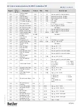
148 

20 

Preset speed 1 

U16 

-P-01 

P-01 

Internal value (3000 = 50.0Hz) 

149 

21 

Preset speed 2 

U16 

-P-01 

P-01 

Internal value (3000 = 50.0Hz) 

150 

22 

Preset speed 3 

U16 

-P-01 

P-01 

Internal value (3000 = 50.0Hz) 

151 

23 

Preset speed 4 

U16 

-P-01 

P-01 

Internal value (3000 = 50.0Hz) 

152 

24 

2nd deceleration 
ramp 

U16 

2500 

250 = 2.50s 

Summary of Contents for X2 base 7

Page 1: ...Quick start guide Modbus TCP communication between X2 control and BFI E3 SER0020 X2 control communication with BFI E3 by Modbus TCP...

Page 2: ...Firmware 3 09 For further information refer to BFI E3 User Guide BFI E3 Start Up Manual KI00369B Installation Manual X2 pro X2 marine X2 control Beijer Electronics knowledge database HelpOnline This...

Page 3: ...Connect BFI Tools to BFI E3 through Ethernet 10 Parameter settings for Modbus TCP in BFI E3 11 Ethernet Cyber Security control 11 8 Function Block X2_BFI_E3_ModbusTCP 12 9 Program example CODESYS BCS...

Page 4: ...h the BFI E3 setting in CODESYS BCS Tools See chapter 6 4 2 Set up parameters in BFI E3 MTP Either set them up on the display of BFI E3 PC software BFI Tools or a device with BFI Tools Mobile See chap...

Page 5: ...port of X2 control X2 control has 2 ethernet ports to be used for Modbus TCP either LAN A or LAN B This program example is using LAN B for Modbus TCP communication IP address setting in X2 control Th...

Page 6: ...ber 63510 General Purpose Inverter 0 37kW 2 3A Input 1x230 V AC Output 3x230 V AC IP66 No Brake transistor EMC Size 1 With Ethernet ports BFI E3 12 0023 1F1A MTP Item number 63510 MTP General Purpose...

Page 7: ...hernet ports in BFI E3 Communication working Communication interruption Network Status Indicator NS State Indication Steady Off BFI is not powered up or no IP address Flashing Green Online no Modbus T...

Page 8: ...er Username is Admin and Password is the serial number of the BFI Module Configuration OPT 3 MTPIG BFI is the name for the internal Modbus TCP board The serial number is the identification for the com...

Page 9: ...gram BFI Tools running on the PC 192 168 1 40 is the IP address of one X2 Control Modbus Statistics Correct working communication without any fault should look like below Counter of Transmitted Receiv...

Page 10: ...s Choose way of communication with BFI 1 Chose Ethernet Module 2 Set the Local PC IP adress to 192 168 1 x were 0 x 250 3 Re Scan Network to find BFI E3s in the network or tap in the IP adress manuall...

Page 11: ...ber Security control There are two parameters P 61 and P 62 intended for cyber security control By combining these two parameters it is possible to restrict access to the Webserver of the drive But Mo...

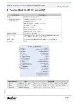
Page 12: ...thernet 3 5 13 0 Modbus_TCP_Master 3 5 13 0 Modbus_TCP_Slave 3 5 12 0 Function Block X2_BFI_E3_ModbusTCP Functionality This function block is used to control and Read Write Data with a BFI E3 MTP by M...

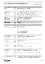
Page 13: ...rom a parameter Output Type Function o_ComOk BOOL Status of Communication o_CommunicationStat e UINT Status of Communication 0 No Slave 1 TCP connect request 2 TCP connection established 3 TCP connect...

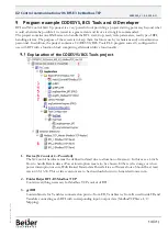
Page 14: ...configured for use with BFI with a function block comprising all standard drive functionality Explanation of the CODESYS BCS Tools project 1 Device X2 control 4 Powerfail The X2 control hardware must...

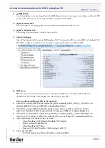
Page 15: ...h physical BFI has an individual IP address in CODESYS BCS Tools corresponds with the setting in each BFI How to add an additional BFI in the network Enter GVL called gvlBFI_HMI Adjust the global cons...

Page 16: ...hen Change name fbControlBFI1 to fbControlBFI5 Change name Drive1 to Drive5 Change name BFI_1 to BFI_5 Change name for all 1 to 5 for all other variables in the network How to remove BFI in the networ...

Page 17: ...Modbus TCP communication If LAN B is used for Modbus TCP either of the settings above can be used Upper example with Adjust Operating System Settings activated the X2 control detects automatically LAN...

Page 18: ...n its Modbus TCP slave configuration 4 Socket Timeout Maximum time to wait for incoming TCP IP packages The bus cycle task can be blocked during this time for example if a Modbus TCP slave is disconne...

Page 19: ...Read of serial number every time communication is established 13 Write parameter number to access when required 14 Read Parameter value when required 15 Write parameter value when required 16 Digital...

Page 20: ...STO in BFI H3 and BFI P2 c Total Running Hours d Motor in Run or Stop e Motor current f Output frequency g If Alarm in BFI it is shown h Explanation of what the alarm means 5 Take control of the BFI f...

Page 21: ...ould look like Check following items Hardware Is the patch cable connected to correct LAN port of X2 control and port P1 of BFI E3 MTP Power on to X2 control Power turned on to BFI E3 MTP Software or...

Page 22: ...I E3 MTP Variable Ready to Run must be 1 to run the BFI E3 Stop in display o Start signal by bus is missing As soon as BFI receives a start signal a value between 0 and Maximum speed is displayed inst...

Page 23: ...00 3 00 16 P00 18 Motor control processor software version U16 03 R 2dp e g 300 3 00 17 P00 20 Drive type U16 03 R Internal Value 18 P00 48 Scope Channel 1 Data S16 03 R See Below 19 P00 48 Scope Chan...

Page 24: ...than run For normal run start just set this register to 1 Note that stat stop bit 0 fast stop bit 1 and coast stop bit 3 only works if P 31 0 or 1 Otherwise start stop function is controlled by drive...

Page 25: ...Modbus registers Register 44 Drive parameter index This index value will be used by register 45 to carry out parameter read and write function The valid range of this parameter is from 1 to 60 maximu...

Page 26: ...ed speed U16 0 30000 Maximum value equals to the sync speed of a typical 2 pole motor 139 11 Boost voltage value U16 0 Drive Dependent 1dp e g 100 10 0 140 12 Control mode U16 0 9 0 Terminal Control 1...

Page 27: ...isplay scaling factor U16 See Below 169 41 User PI P gain U16 1 300 1dp e g 10 1 0 170 42 User PI I time constant U16 0 300 1dp e g 10 1 0s 171 43 User PI mode select U16 0 1 See user guide for more i...

Page 28: ...Injection Configuration The parameter value is stored as a combined 16 bit word which is constructed as follows Register 164 which is Parameter P 36 Communications Configuration This Register entry c...

Page 29: ...write a register that does not exist within the drive Exception Code 3 Register Value Out of Range Returned under the following conditions Network Master attempts to write a holding register with a va...

Page 30: ...00 1 00kW 148 20 Preset speed 1 U16 0 P 01 03 R 3000 50 0Hz Register Parameter Description Format Min Max Data format Scaling 134 06 Reserved No Function 139 11 Boost Value U16 0 Drive Rating Dependen...

Page 31: ...s in user friendly software hardware and services for the Industrial Internet of Things we empower you to meet your challenges through leading edge solutions Beijer Electronics is a Beijer Group compa...

Reviews: