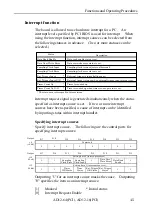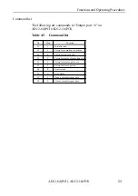
Functions and Operating Procedures
AD12-64(PCI), AD12-16(PCI)
49
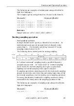
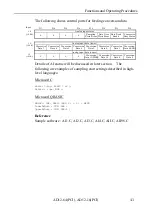
The following shows control ports for starting timer:
The following shows control ports for stopping timer:
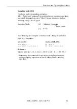
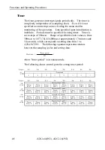
The following are examples of timer period settings described in
high-level languages:
Microsoft C
outp( ADR+8, 5 );
outp( ADR+12, ClockData0 );
outp( ADR+13, ClockData1 );
outp( ADR+14, ClockData2 );
outp( ADR+15, ClockData3 );
outp( ADR+8, 6 );
:
outp( ADR+8, 7 );
Microsoft QBASIC
OUT ADR+8 5
Timer period settings
OUT ADR+12 ClockData0
OUT ADR+13 ClockData1
OUT ADR+14 ClockData2
OUT ADR+15 ClockData3
OUT ADR+8 6
Timer start
:
OUT ADR+8 7
Timer stop
Reference
Sample software : TI.C, TI98.C
+8
(+08h)
0
0
0
0
1
1
0
0
Output
D 7
D 6
D 5
D 4
D 3
D 2
D 1
D 0
Command
+8
(+08h)
0
0
0
0
1
1
0
1
Output
D 7
D 6
D 5
D 4
D 3
D 2
D 1
D 0
Command
Summary of Contents for AD12-16(PCI)
Page 1: ...AD12 64 PCI AD12 16 PCI 64 16 Channel Analog to Digital Input Board for PCI User s Guide...
Page 61: ...Functions and Operating Procedures AD12 64 PCI AD12 16 PCI 54...
Page 67: ...Calibration Procedures AD12 64 PCI AD12 16 PCI 60...
Page 71: ...System Reference AD12 64 PCI AD12 16 PCI 64...
Page 74: ...Index AD12 64 PCI AD12 16 PCI...
Page 75: ...A 46 068 LZJ3711 021011 991104...

