Sensor-
Settings / Type „Modbus“
PI 500
Seite
52
von
93
Main menu
Settings
Sensor settings
C1
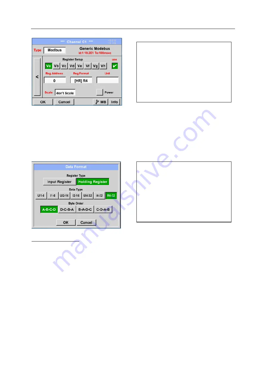
Reg. Address description field
Important:
Required is the correct
register-address
.
It should be noted that the register-number could be different to the register-address (Offset).
For this, please consult the sensor data sheet.
Main menu
Settings
Sensor settings
C1
Reg. Format description field
Supported Data types:
Data Type
:
UI1(8b) = unsigned Integer => 0 - 255
I1 (8b) = signed integer
=> -128 - 127
UI2 (16b) = unsigned Integer => 0 - 65535
I2 (16b) = signed integer
=> -32768 - 32767
UI4 (32b) = unsigned Integer => 0 - 4294967295
I4 (32b) = signed integer
=> -2147483648 - 2147483647
R4 (32b) = floating point number
Byte Order
:
The size of each Modbus-register is 2 Byte. For a 32 bit value two Modbusregister will be read out by
the DS500. Accordingly for a 16bit Value only one register is read.
In the Modbus Specification, the sequence of the transmitted bytes is not defined clearly. To cover all
possible cases, the byte sequence in the DS500 is adjustable and must adapted to the respective
sensor. Please consult here for the sensor datasheet.
e.g.: High byte before Low Byte, High Word before Low Word etc.
Therefore the settings have to be made in accordance to the sensor data sheet.
The measurement values are kept in the
registers of the sensor and can be
addressed via Modbus and read by the
PI 500
This requires setting the desired register
addresses in the PI 500
Entering the register / data address is here
in decimal with 0-65535.
With the buttons
Input Register
and
Holding
Register
the corresponding Modbus-register
type will be selected.
The number format and transmission order
of each value needs to be defined by
Data
Type
and
Byte Order.
Both have to be
applied in correct combination.


