S1C63656 TECHNICAL MANUAL
EPSON
123
CHAPTER 4: PERIPHERAL CIRCUITS AND OPERATION (Stepping Motor Driver)
4.15.3 Pulse output control
Ch. 1 starts outputting a pulse by writing "1" to the FTRG1 bit (FF10H•D0).
The motor driver starts executing a pulse output sequence using this writing as a trigger, and a pulse is
output from the AO1 or AO2 terminal in the timing shown in the figure below. The first motor-drive
pulse after an initial reset is output from the AO1 terminal. The following pulses are output from AO2
and AO1 terminals alternately every time "1" is written to FTRG1.
The FTRG1 bit used to trigger a pulse output is used as the status bit FRUN1 that indicates the motor
driver status when reading. FRUN1 is set to "1" when the motor driver starts a pulse output sequence and
is cleared to "0" upon completion of a pulse output for the specified width. At this time, an interrupt can
be generated.
Ch. 2 can also be controlled with exactly the same method but FTRG2/FRUN2 (FF10H•D1) is used
instead of FTRG1/FRUN1. The motor-drive pulses are output from the BO1 and BO2 alternately.
Writing "1" to
FTRG1/FTRG2
FRUN1/FRUN2
AO1/AO2/BO1/BO2
ISMD1/ISMD2
When PFTYP = "1":
Interrupt
Max. 0.2 msec
0.13 msec
1.46–7.08 msec
Writing "1" to
FTRG1/FTRG2
FRUN1/FRUN2
AO1/AO2/BO1/BO2
ISMD1/ISMD2
When PFTYP = "0":
Interrupt
Max. 1.0 msec
0.98 msec
11.72–56.64 msec
Fig. 4.15.3.1 Motor-drive pulse output timing chart
4.15.4 Interrupt function
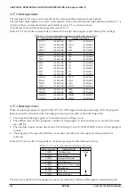
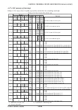
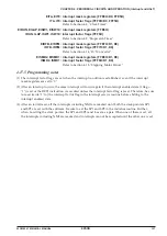
This motor driver has an interrupt function in each channel. As shown in Figure 4.15.3.1, the interrupt
factor flag ISMD1 (Ch. 1)/ISMD2 (Ch. 2) is set to "1" upon completion of a pulse output triggered by
writing "1" to the FTRG1/FTRG2 bit and an interrupt is generated. The interrupt can also be masked by
setting the corresponding interrupt mask register EISMD1/EISMD2. However, the interrupt factor flag is
set to "1" upon completion of a pulse output from the corresponding channel regardless of the interrupt
mask register setting.


