Functional Description
ComTec GmbH
4-1
4. Functional
Description
4.1. Introduction
The MPA4 includes two major sections that will be described separately.
1) External ADC interfaces with MPA functionality
2) Additional 100MHz counters / scalers (option) and Digital I/O's
The measured ADC data is transferred into the computer in list-mode, i.e. as they are acquired
per each input channel.
4.2. MPA Modes of Operation
There are two basic modes available with the external ADC interfaces: SINGLE and
COINCIDENCE mode and any combination of them. Each interface may be simultaneously used
in both modes.
For Livetime correction every 1ms the DEADTIME signals of each port are sampled and
transferred to the PC.
4.2.1. SINGLE
Mode
In SINGLE mode of operation each ADC data is simply transferred to the PC as it arrives.
The data maybe tagged with 32 bit of the Real Time Clock. Thus, the timely development of the
events maybe analyzed.
And 9 least significant bits of the TOF sweep counter value maybe included which is important in
the combined TOF and MPA mode of operation.
4.2.2. COINCIDENCE
Mode
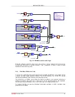
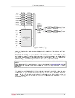
The basic purpose of introducing COINCIDENCE mode is to acquire only data that meets some
predefined timing relationship.
Events that will be accumulated must occur inside the coincidence resolving time window. Thus,
events that do not fall in this coincidence time window will be discarded and do not show up in the
acquired histograms.
The versatility of the coincidence definitions in the MPA4 system allows to select various
combinations of ADC events that either have to occur within the coincidence time window or
where just some have to occur to accumulate them.
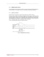
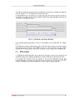
In COINCIDENCE mode of operation the active going edge (programmable rising or falling edge)
of the ADC's DEADTIME signal is used as time-of-arrival of an ADC event. This is done because
the DEADTIME signal usually is the most accurate time information obtainable from an ADC.
On detecting an active going edge of a DEADTIME signal a coincidence resolving time window is
opened. While a coincidence window is open all arriving DEADTIME edges are stored. After the
coincidence time has elapsed the system waits for all DRDY signals of the corresponding ADC
ports (meaning that the port contains valid data) to become true. The maximum time to wait for
this is software selectable (ref. DRDY timeout chapter 5.1.5). When all expected DRDYs have
arrived - or at the latest when the DRDY timeout elapsed – the corresponding data is transfered
to the PC in listmode. If a port has no new data (DRDY did not go active until the timeout
occurred) a zero is transfered for this port.

