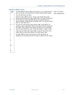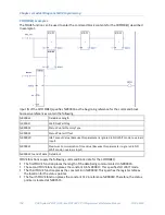
Chapter 4. Ladder Diagram (LD) Programming
152
PACSystems* RX7i, RX3i and RSTi-EP CPU Programmer's Reference Manual
GFK-2950C
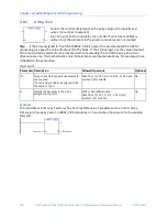
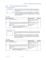
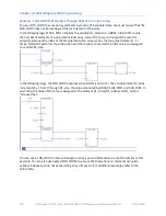
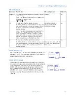
Command Block Structure
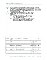
Address
Data Block Length
(in words)
The number of data words starting with the data at 6 to the
end of the command block, inclusive. The data block length ranges
from 1 to 128 words. Each COMMREQ command has its own data
block length. When entering the data block length, you must ensure
that the command block fits within the register limits
A 1
Wait/No Wait Flag
Must be set to 0 (No Wait)
A 2
Status Pointer
Memory Type
Specifies the memory type for the location where the COMMREQ
status word (CSR) returned by the device will be written when the
COMMREQ completes.
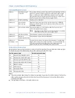
A 3
Status Pointer Offset The word at a 3 contains the offset for the status word
within the selected memory type.
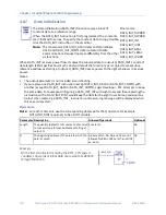
Note:
The status pointer offset is a zero-based value. For example,
%R00001is at offset zero in the register table.
A 4
Idle Timeout Value
This parameter is ignored in No Wait mode.
A 5
Maximum
Communication Time
This parameter is ignored in No Wait mode.
A 6
to A 133
Data Block
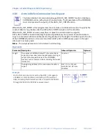
The data block contains the command's parameters. The data block
begins with a command number in a 6, which identifies the
type of communications function to be performed. Refer to the
specific device manual for COMMREQ command formats.
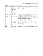
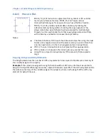
Status Pointer Memory Type
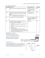
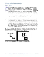
Status pointer memory type contains a numeric code that specifies the user reference memory type
for the status word. The table below shows the code for each reference type:
For this memory type
Enter this decimal value
%I
Discrete input table (BIT mode)
70
%Q
Discrete output table (BIT mode)
72
%I
Discrete input table (BYTE mode)
16
%Q
Discrete output table (BYTE mode)
18
%R
Register memory
8
%W
Word memory
196
%AI
Analog input table
10
%AQ
Analog output table
12
Notes:
■
The value entered determines the mode. For example, if you enter the %I bit mode is 70, then the
offset will be viewed as that bit. On the other hand, if the %I value is 16, then the offset will be
viewed as that byte.
■
The high byte at a 2 should contain zero.
Summary of Contents for PACSystems RSTi-EP
Page 357: ......
Page 466: ...Chapter 9 Diagnostics GFK 2950C February 2018 451 ...


