User’s Manual
GT-650 WatchDog Timer D - 3
CRF6 (Default 0x00)
Watchdog timer time out value. Writing a non-zero value to this register causes
the counter to load the value to Watchdog Counter and start counting down. If
the Bit 7 and Bit 6 are set, any mouse interrupt or Keyboard Interrupt event will
also cause the reload of previously-loaded non-zero value to Watchdog Counter
and start counting down. Reading this register returns current value in
Watchdog Counter instead of Watchdog Timer time-out value.
Bit 7-0:
= 0x00
Time-out Disable
= 0x01
Time-out occurs after 1 second/mintue
= 0x02
Time-out occurs after 2 second/mintue
= 0x03
Time-out occurs after 3 second/mintue
.
.
.
= 0xFF
Time-out occurs after 255 second/mintue
CRF7 (Default 0x00)
Bit 7: Mouse interrupt reset Enable or Disable
= 1
Watchdog Timer is reset upon a Mouse interrupt
= 0
Watchdog Timer is not affected by Mouse interrupt
Bit 6: Keyboard interrupt reset Enable or Disable
= 1
Watchdog Timer is reset upon a Keyboard interrupt
= 0
Watchdog Timer is not affected by Keyboard interrupt
Bit 5: Force Watchdog Timer time-out, write only*
= 1
Force Watchdog Timer time-out event, this bit is
self-clearing.
Bit 4: Watchdog Timer Status, R/W
= 1
Watchdog Timer time-out occurred.
= 0
Watchdog Timer counting.
Bit 3-0: These bits select IRQ resource for Watchdog. Setting of 2 selects SMI.
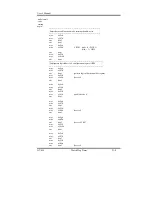
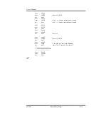
Software programming example
The following example is written in Intel 8086 assembly language. It assumes
that the EFER is located at 2Eh, so the EFIR is located at 2Eh and EFDR is
located at 2Fh. It will reset the system in 30 seconds. We can use both keyboard
interrupt and mouse interrupt to cause the watchdog to reload and start to count
down from the value of CRF6.
Summary of Contents for GT-650
Page 1: ...GT 650 Pentium III Celeron w VGA LAN Audio w Video Capture GPIO Embedded Board User s Manual ...
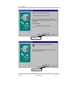
Page 59: ...User s Manual GT 650 Software Setup 5 2 Click on Yes Click on Next ...
Page 60: ...User s Manual GT 650 Software Setup 5 3 Click Finish to restart computer ...
Page 61: ...User s Manual GT 650 Software Setup 5 4 For Windows NT 4 0 system Click on Yes Click on Next ...
Page 62: ...User s Manual GT 650 Software Setup 5 5 Click Finish to restart computer ...
Page 64: ...User s Manual GT 650 Software Setup 5 7 Click Finish to restart computer ...
Page 67: ...User s Manual GT 650 Software Setup 5 10 Click on Next Click on Next ...
Page 68: ...User s Manual GT 650 Software Setup 5 11 Click Finish ...
Page 74: ...User s Manual GT 650 Software Setup 5 17 Click on Finish Click on Yes to restart computer ...
Page 75: ...User s Manual GT 650 Software Setup 5 18 5 4 2 For Windows 2000 system Click on System ...
Page 78: ...User s Manual GT 650 Software Setup 5 21 Click on Next Click on Next ...
Page 79: ...User s Manual GT 650 Software Setup 5 22 Specify the PATH by Browser Locate the INF file ...
Page 80: ...User s Manual GT 650 Software Setup 5 23 Click on Next Click on Finish ...
Page 81: ...User s Manual GT 650 Software Setup 5 24 Click on Close ...
Page 83: ...User s Manual GT 650 Software Setup 5 26 Click on Add Click on Have Disk ...
Page 88: ...User s Manual GT 650 Software Setup 5 31 Click on Next Click Browse to specify PATH ...
Page 89: ...User s Manual GT 650 Software Setup 5 32 Click on Next Click OK ...
Page 93: ...User s Manual GT 650 Software Setup 5 36 Click on Next Click on Next ...
Page 94: ...User s Manual GT 650 Software Setup 5 37 Click on Next Click on Finish ...
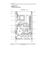
Page 111: ...User s Manual GT 650 Mechanical drawing E 1 Appendix E Mechanical Drawing ...

