Instruction Manual PSx3xxEIP
28
2.9.6. Parameter interface
Via the parameter interface it’s possible to write and read parameter values by using
the cyclic process data connection, besides, also other values might be retrieved from
the drive.
With the help of the parameter interface the EIP scanner sets and transmits a new
command. It repeats this command cyclically until the drive has processed the
command and has sent back an answer. The drive provides this answer until the EIP
scanner formulates a new command. A parameter value that’s being sent back by the
the drive as an answer to a read request, refers to the moment at which the EIP
scanner has been issued the command. I.e. in case of a parameter value that should
be monitored for a longer time, the EIP scanner has to send another command after
taken over the actual parameter value. This takes place by setting the request
identifier 0 (“no request”) and subsequent waiting, until the drive confirms this request
with the response identifier 0 (“no response”). Afterwards the same parameter value
might be requested again.
One drive can only process one request at a time.
Structure of the parameter interface:
Parameter interface
PKE
IND
PWE
0 1 2 3 4 5 6 7
PKE = Parameter identifier
IND = Index
PWE = Parameter value
Structure of the parameter identifier PKE:
The information “parameter identifier” (PKE) consists of a data word (byte 0 and 1 of
the parameter interface), in which the type of the request (or the response) and the
related parameter number are coded:
Parameter identifier PKE
Bit No.
15 14 13 12
11
10 9 8 7 6 5 4 3 2 1 0
AK
SPM
Parameter number (PNU)
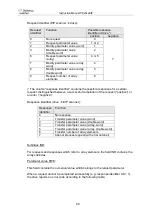
AK = request identifier or response identifier
SPM
not used, set to 0
PNU = Parameter number
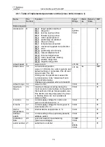
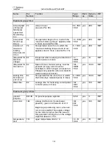
The parameter number (PNU) refers to the table above
(“Table of implemented
parameter entries (class 0x64; instance 1)”).

