


Chapter 7 Exclusive Functions for iS7 Inverter Control/Monitoring
7-16
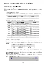
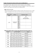
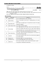
2) The APO76 (PLC Rd Data1) corresponds by 1:1 with the D4474 which is the special register of PLC
option. Therefore, the value in the D4474 is the data (inverter digital input status) stored in the
0320Hex which is the address of the inverter digital input status registered in the APO76 (PLC Rd
Data1).
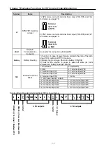
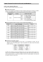
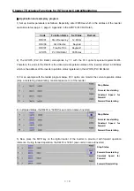
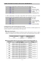
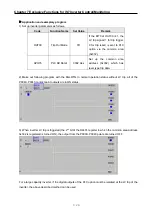
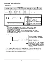
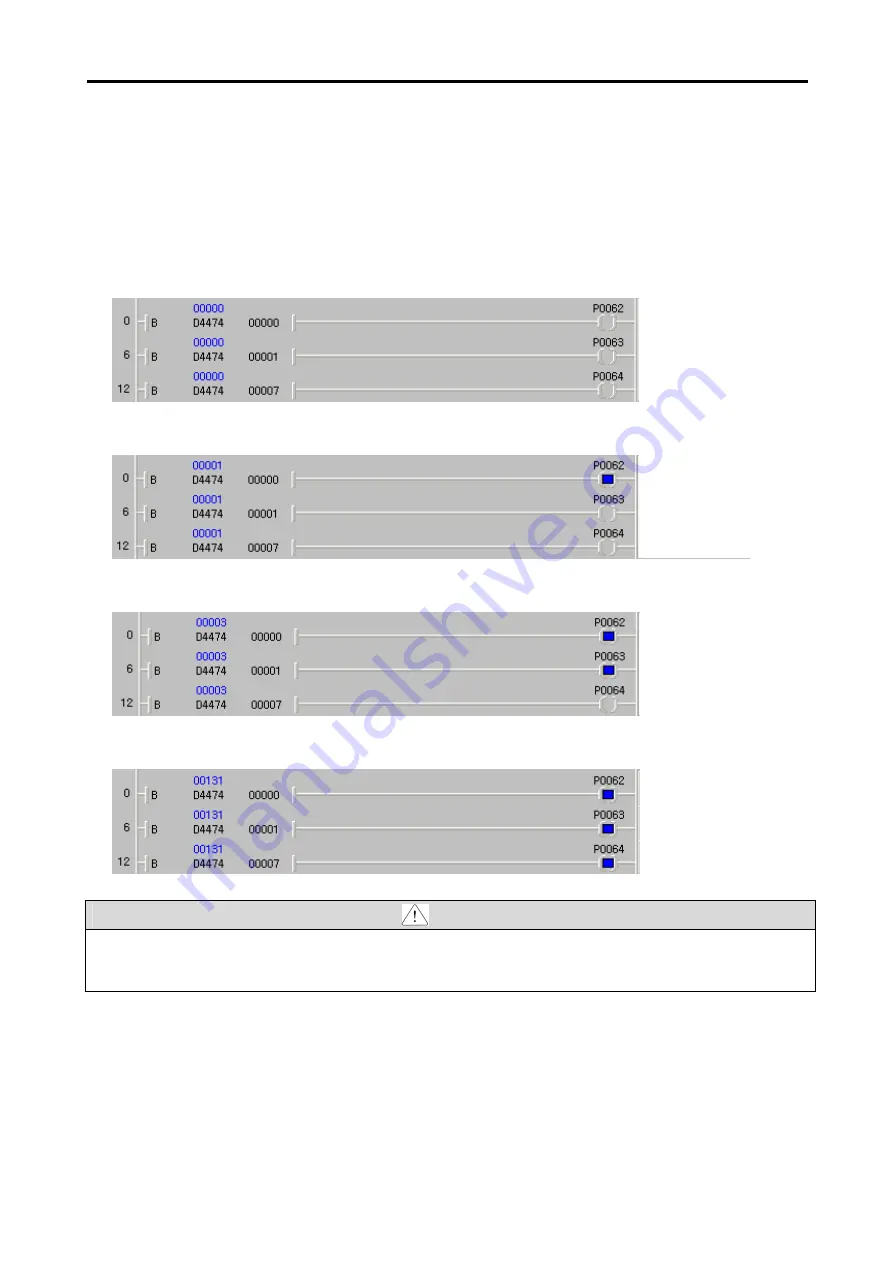
3) For an example with the ladder program below, PLC option can monitor the digital input status (0 or
1) of the inverter.
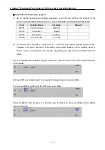
4) When the inverter’s multifunction input P1 is ON, the P0062 coil is excited as shown below.
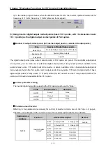
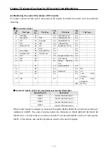
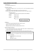
5) When the inverter’s multifunction input P2 is ON, the P0063 coil is excited as shown below.
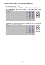
6) When the inverter’s multifunction input P8 is ON, the P0064 coil is excited as shown below.
Caution
The scanning frequency of PLC option card reading the digital input points of inverter is approximately
10ms.
Status of P2 (IN66):
0 (Off), 1 (On)
Status of P1 (IN65):
0 (Off), 1 (On)
Status of P8 (IN72):
0 (Off), 1 (On)
Status of P2 (IN66):
0 (Off), 1 (On)
Status of P1 (IN65):
0 (Off), 1 (On)
Status of P8 (IN72):
0 (Off), 1 (On)
Status of P2 (IN66):
0 (Off), 1 (On)
Status of P1 (IN65):
0 (Off), 1 (On)
Status of P8 (IN72):
0 (Off), 1 (On)
Status of P2 (IN66):
0 (Off), 1 (On)
Status of P1 (IN65):
0 (Off), 1 (On)
Status of P8 (IN72):
0 (Off), 1 (On)


