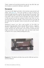
Here is an overview of the APM and all of the inputs/outputs (I/Os):
Inputs 1–8
These ports will be connected to our radio receiver. This col-
lects our flight instructions from the ground and delivers
them to the APM.
GPS
This port will be connected to our GPS sensor.
I2C (inter-integrated circuit, pronounced I-squared-C)
This is a standardized serial computer bus that is used for
many types of peripherals. If you have used an Arduino
before, you may be familiar with the I2C protocol. We will be
using this port for our external compass.
PM
This is our power module port. This allows us to monitor our
power supply.
JP1
This is a jumper port used to tell the APM if there should be
a power module in use.
Outputs1–8
These will supply the signal we need for our electronic speed
controllers. Alternatively, these could send a signal to a set
of servos if you used APM for a model airplane or inputs to a
gimbal controller if you asked APM to control a camera
mount on your drone.
Telem
Our telemetry radio plugs in here.
A0–A11
Just as in an Arduino, these are our user assignable analog
pins. These will not be used in this book.
Flight Controller 81
Summary of Contents for Belinda Kilby
Page 1: ......
Page 3: ...Make Getting Started with Drones Terry Kilby and Belinda Kilby...
Page 26: ......
Page 90: ......
Page 126: ......
Page 153: ...Figure 9 10 Compass setup Figure 9 11 Compass calibration ArduPilot Mega APM Setup 141...
Page 198: ......

