6.1.1
Control word (STW)
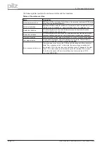
With the aid of the control word, you can switch from one instrument state to another. In the dia-
gram for the state machine you can see which instrument states can be reached by which transi-
tions. The momentary instrument state can be taken from the status word.
Several states may be passed through during a telegram cycle (e.g. Ready for switch on
®
Ready
for operation
®
Operation enabled).
The bits in the control word can be (operating-)
mode-dependent
or
mode-independent
.
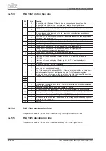
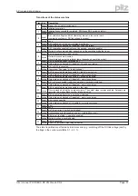
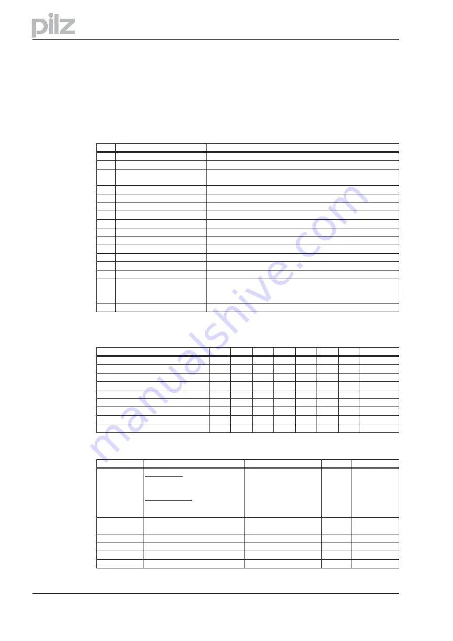
The following table describes the bit assignment in the control word.
Bit
Name
Commentary
0
Switch on
—
1
Inhibit voltage
—
2
Fast stop, switch-on inhibited
1 -> 0
drive brakes using emergency ramp, axis is disabled
(See also ASCII-commands STOPMODE and DECDIS)
3
Operation enabled
—
4
Fast stop (inhibit rfg)
1 -> 0
drive brakes using emergency ramp
5
Pause (stop rfg)
Mode-dependent, 1 -> 0 stops motion
6
Setpoint enable
mode-dependent
7
Reset Fault
only effective with errors
8
Jogging (on/off)
mode-dependent
9
reserved
—
10
PZD (enable/inhibit)
—
11
Start homing run (edge)
mode-dependent
12
Manufacturer-specific
reset the position
13
Manufacturer-specific
acknowledge warnings
14
Manufacturer-specific
only position mode: Bit14 = 1: PZD section is interpreted as direct
motion block (velocity 32-bit, position 32-bit, motion block type 16-bit
Bit14 = 0: PZD section (HSW) is interpreted as motion block number
15
Manufacturer-specific
mode-dependent, digital speed
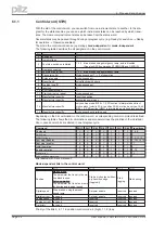
Depending on the bit combination in the control word, a corresponding control command is defined.
The following table shows the bit combinations and also determines the priorities of the individual
bits, in case several bits are altered in one telegram cycle.
Command
Bit 13
Bit 7
Bit 4
Bit 3
Bit 2
Bit 1
Bit 0 Transitions
Shutdown
X
X
X
X
1
1
0
2, 6, 8
Switch-on
X
X
X
X
1
1
1
3
Inhibit voltage
X
X
X
X
X
0
X
7, 9, 10, 12
Fast stop (disable)
X
X
X
X
0
1
X
7, 10,11->12
Fast stop (enable)
X
X
0
1
1
1
1
11
Inhibit operation
X
X
X
0
1
1
1
5
Enable operation
X
X
1
1
1
1
1
4, 16
Reset error
X
1
X
X
X
X
X
15
Acknowledge warnings
1
X
X
X
X
X
X
-
Bits labeled with X are irrelevant.
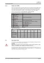
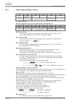
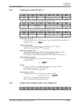
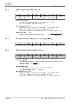
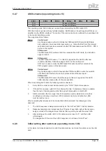
Mode-dependent bits in the control word:
Mode
Bit 5
Bit 6
Bit 8
Bit 11
Position
Motion block
:
The parameter that is set in the mo-
tion block is used.
Setup operation
:
The parameter that is set as a ramp
for homing and jogging is used
Start a motion task with ev-
ery transition edge
(toggle bit).
Start
jogging
Start homing
Digital speed
Drive brakes, using the preset
speed ramp.
Setpoint enable
reserved
reserved
Digital current
reserved
Setpoint enable
reserved
reserved
Analog speed
reserved
reserved
reserved
reserved
Analog current
reserved
reserved
reserved
reserved
Trajectory
reserved
reserved
reserved
reserved
Priority of the Bits 6, 8, 11 in position-control mode: 6 (high), 11, 8 (low).
Page 38
User manual PROFIBUS DP PMCtendo DD4
6 Process data channel

