Page 14 / 28
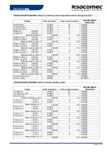
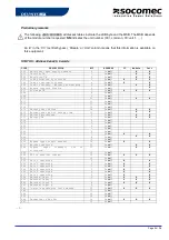
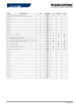
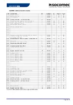
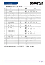
STANDARD JBUS/MODBUS TABLES FOR SINGLE UNIT UPS
In parallel of the extended tables, it’s also possible reading the standard JBUS/MODBUS, according the
following tables.
STANDARD JBUS/MODBUS tables
§
TABLE
Start
addresses
Table length in
words
JBUS/MODBUS
FUNCTION
1
UPS Identification
0x0000
12
3 READ
2
Date and hours
0x0360
4
3 READ
3
UPS Configurations
0x00E0
32
3 READ
4
Status (96 bits)
0x0020
6
3 READ
5
Alarms (64 bits)
0x0040
4
3 READ
6
Measurements
0x0060
48
3 READ
7
Controls permission
0x05C0
2
3 READ
8
UPS Controls
0x05B0
1
6 WRITE
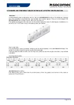
How to read data:
The identification, status and alarms tables should be read completely (this means the number of word to
read is equal to the table length).
The measurements table could be read word by word or per group, without exceed the length of the table.
(from 0x0060 to 0x008F).
Incoming data structure:
Example of 6 words
1
2
3
4
5
6
7
8
9
10
11
12
MSB 0
LSB 0
MSB 1
LSB 1
MSB 2
LSB 2
MSB 3
LSB 3
MSB 4
LSB 4
MSB 5
LSB 5
WORD 0
WORD 1
WORD 2
WORD 3
WORD 4
WORD 5
b15
b0
b15
b0
b15
b0
b15
b0
b15
b0 b15
b0
S15
S00
S31
S16
S47
S32
S63
S48
S79
S64 S95
S80
A15
A00
A31
A16
A47
A32
A63
A48
M00
M01
M02
M03
M04
M05
‘Concentrator mode’ in parallel system configuration
The above
J
J
B
B
U
U
S
S
/
/
M
M
O
O
D
D
B
B
U
U
S
S
table can be used in case of a parallel system configuration. The TOR data
from all units or modules are managed in order to create a ‘virtual single unit’. The logic combination ‘
OR
’ is
used to create the single unit data base, except following states and alarms :
Information
Combination if redundant UPS
Combination if not redundant UPS
S00
OR
AND
S05
AND
OR
S15
AND
OR
A02
AND
OR
A07
AND
OR
A31
AND
OR


